
Method of film deposition on substrate surface and substrate produced by the method

a technology of substrate surface and film deposition method, which is applied in the direction of vacuum evaporation coating, coating, electrolysis components, etc., can solve the problems of unstable glow discharge plasma, and inability to achieve the desired thickness of coating film

Inactive Publication Date: 2003-07-01
NIPPON SHEET GLASS CO LTD +1
View PDF9 Cites 32 Cited by
  • Summary
  • Abstract
  • Description
  • Claims
  • Application Information

AI Technical Summary

Problems solved by technology

In the sputtering method described above, the glow discharges generated for sputtering target materials are not stable, i.e., an abnormal discharge generates frequently.
The conventional technique hence has had a problem that a coating film having a desired thickness cannot be obtained or the coating film deposited has pinholes or adherent foreign substances.
This covering causes the glow discharge plasma to be unstable and unable to last.
Namely, there has been a problem that stable and continuous film deposition becomes impossible.
This problem is serious especially when an oxide coating film or a semiconductor coating film is to be deposited on a substrate, and brings about fatal results.
Specifically, abnormal discharges frequently occur and glow discharges stop occasionally, making it impossible to continue coating film deposition.
However, the increased distance between cathodes poses an essential problem that the target materials respectively ejected from the two targets cannot be simultaneously sputtered as a coating film.

Method used


Image

  • Method of film deposition on substrate surface and substrate produced by the method
  • Method of film deposition on substrate surface and substrate produced by the method
  • Method of film deposition on substrate surface and substrate produced by the method

Examples


example 2

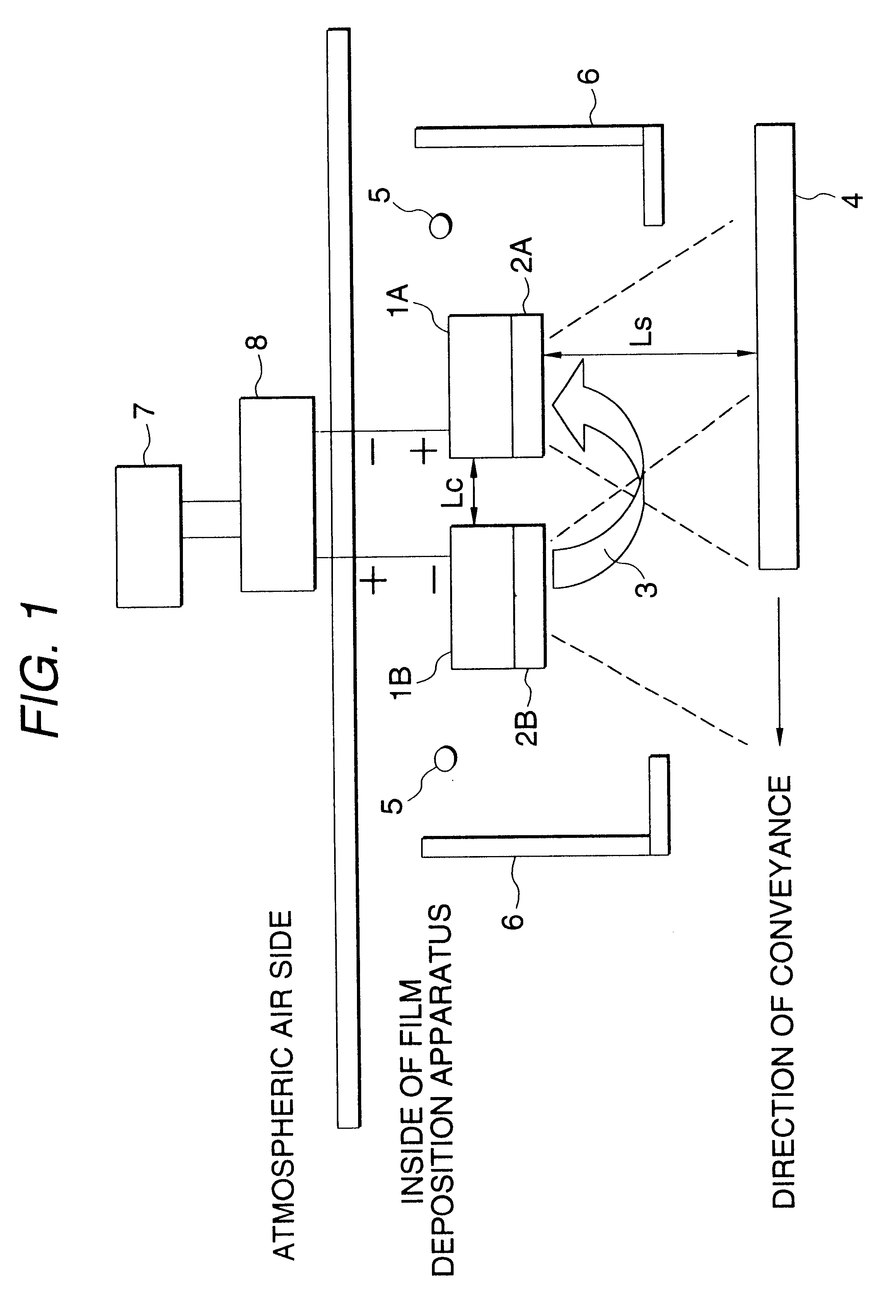
A sintered body of a mixture of indium oxide and a small proportion of tin oxide is used as a target 2A, and a sintered body of a mixture of tin oxide and a small proportion of antimony oxide is used as a target 2B. A mixed gas comprising argon and a small amount of oxygen is used to conduct sputtering simultaneously using the two targets while a glass plate as a substrate is being conveyed in one direction so as to pass in front of the targets. By this method, a coating film is obtained which has a substrate-side layer comprising ITO (low-resistance layer) and a surface-side layer comprising tin oxide (containing a slight amount of antimony oxide; the layer has high resistance to acids and alkalis and excellent marring resistance) and has, in a thickness-direction central part thereof, a gradient-composition boundary where the ITO content and the tin oxide content decreases and increases, respectively, from the substrate side toward the surface side. This coating film can be used a...

example 3

An alloy of barium (Ba) and strontium (Sr) is used as a target 2A, and titanium (Ti) metal is used as a target 2B. Amixed gas comprising argon and a small amount of oxygen is used to conduct sputtering simultaneously using the two targets while a substrate is being conveyed in one direction so as to pass in front to the targets. By this method, a coating film is obtained which has a substrate-side layer comprising an oxide containing barium and strontium and a surface-side layer comprising titanium oxide and has, in a thickness-direction central part thereof, a region where the composition changes continuously from the substrate side toward the surface side. The two sides of this coating film differ in dielectric characteristics. This coating film can be used as a ferroelectric film useful in memories and piezoelectric devices, wherein the ferroelectric film is required to have continuous and asymmetric dielectric characteristics.

An example of mixture films which can be deposited us...

example 4

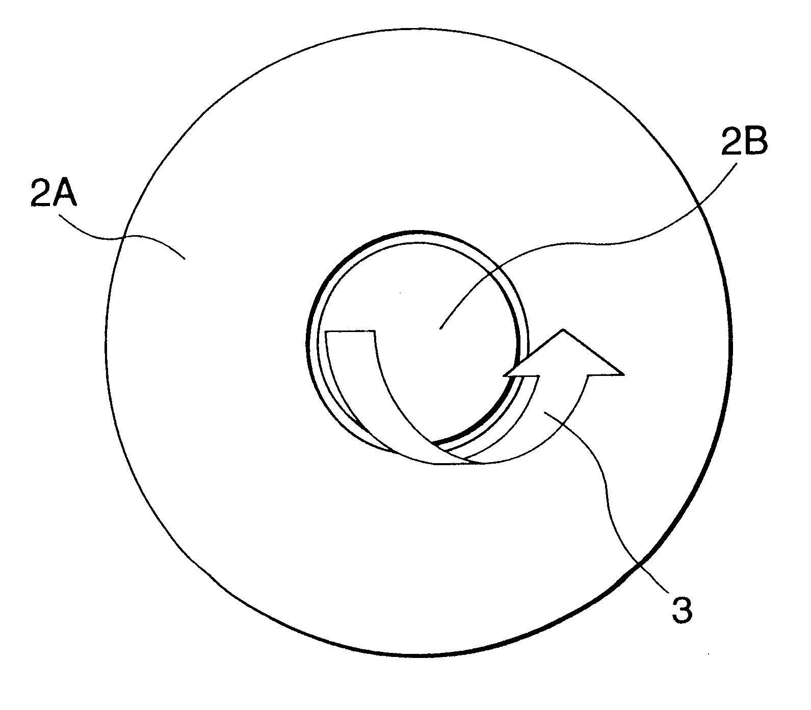
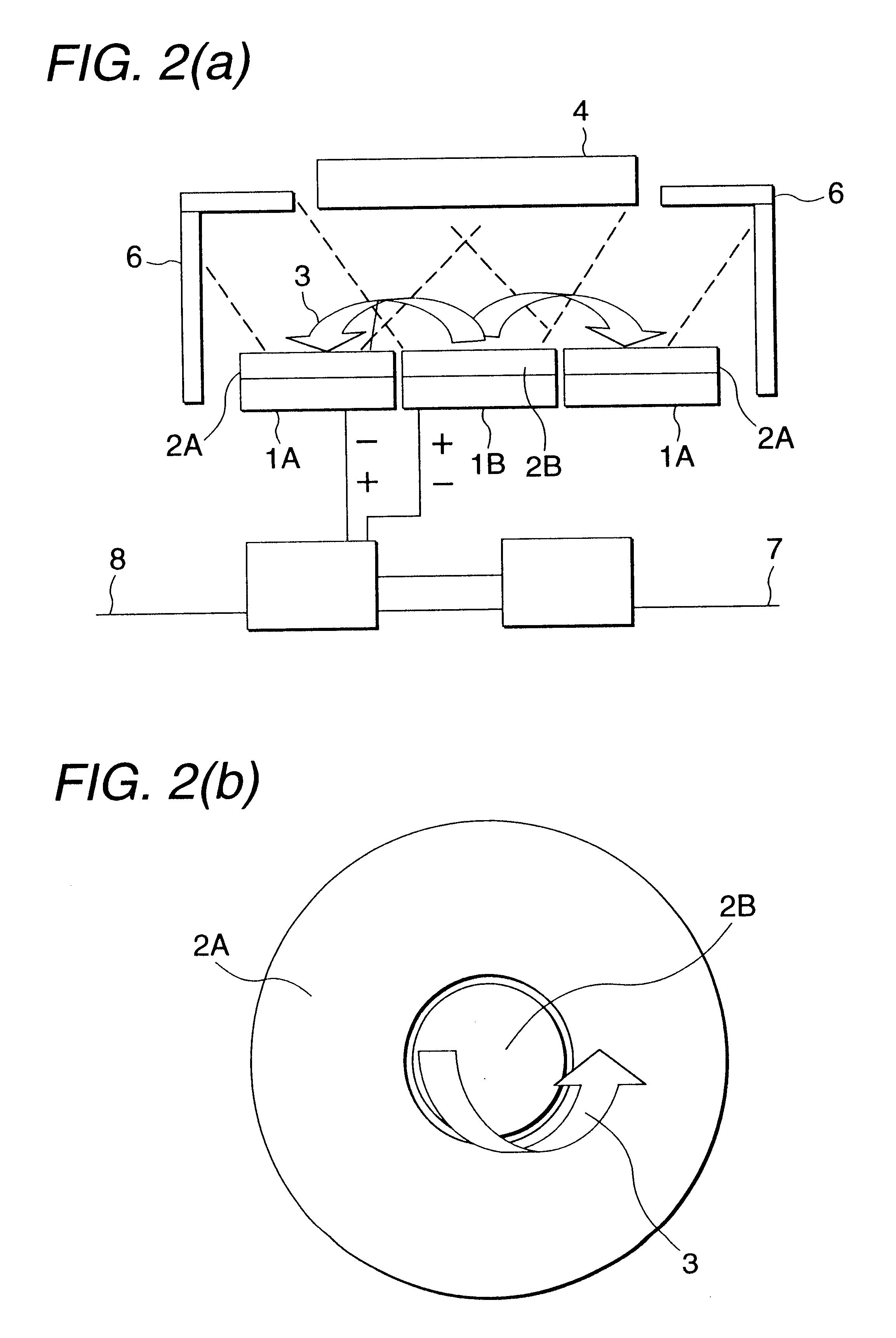
An indium oxide sintered is used as an outer ring-form target 2A, and a tin oxide sintered body is used as an inner disk-form target 2B. A mixed gas comprising argon and a small amount of oxygen is used to conduct sputtering simultaneously using the two targets while a glass plate as a substrate is held so as to face the targets. Thus, a coating film comprising a mixture of indium oxide and tin oxide is deposited on the substrate. This coating film can be used as a transparent conductive film for electronic devices.

Other examples of coating films obtained by practicing the present invention are shown in Table 1 together with Examples 1 to 4. The coating films of Examples 5 to 7 are useful as dielectric layers (protective films) in electromagnetic shielding or heat shielding films formed, for example, by alternately superposing a silver film and a metal oxide film.


PUM

PropertyMeasurementUnit
Thicknessaaaaaaaaaa
Polarityaaaaaaaaaa
Concentrationaaaaaaaaaa

Abstract

A method of film deposition is disclosed, which eliminates the conventional problem that a coating film having a component concentration gradient in the thickness direction and thus having a boundary with a compositional gradient or a coating film in which two or more components coexist as a mixture thereof cannot be stably obtained by sputtering. In the method, two planar cathodes are closely arranged as a pair, and a voltage is applied thereto while alternately inverting the polarities thereof so that when a target A bonded to one of the cathodes is used as a negative electrode, then a target B bonded to the other cathode and differing to the target A in component is used as a positive electrode. The targets A and B are simultaneously bombarded with positive ions while passing a substrate in front of the targets so as to cross the cathodes. Thus, a coating film having a boundary with a compositional gradient in the thickness direction or a coating film having a two-layer structure composed of a layer of ingredient A and a layer of ingredient B is deposited by sputtering through one-direction conveyance.

Description

The present invention relates to a method of depositing a coating film on a substrate by sputtering in a vacuum apparatus which can control a reduced pressure atmosphere.DESCRIPTION OF THE RELATED ARTA technique has conventionally been attempted which comprises closely arranging two cathodes, disposing targets made of different materials respectively on the cathodes, and depositing a coating film comprising the materials of the targets on a substrate by sputtering. In this case, a power supply for applying a negative voltage to each cathode is used. Namely, this technique employs separate electrical circuits for the respective cathodes.In the sputtering method described above, the glow discharges generated for sputtering target materials are not stable, i.e., an abnormal discharge generates frequently. The conventional technique hence has had a problem that a coating film having a desired thickness cannot be obtained or the coating film deposited has pinholes or adherent foreign sub...

Claims


Application Information

Patent Timeline
IPC IPC(8): C23C14/35C23C14/02H01J37/34H01J37/32C23C14/34
CPCC23C14/027C23C14/352H01J37/3405H01J37/3429
Inventor ANZAKI, TOSHIAKIOGINO, ETSUOTOYOSHIMA, TAKAYUKI
Owner NIPPON SHEET GLASS CO LTD
Features
  • Generate Ideas
  • Intellectual Property
  • Life Sciences
  • Materials
  • Tech Scout
  • Unparalleled Data Quality
  • Higher Quality Content
  • 60% Fewer Hallucinations
Learn More