
Silica glass crucible and method of fabricating thereof

a technology glass crucible, which is applied in the field of silica glass crucible, can solve the problems of deformation of the silica glass crucible, unstable conversion to single crystal, and eroded silica glass crucible surface by silicon mel

Inactive Publication Date: 2003-11-25
COVALENT MATERIALS CORP
View PDF10 Cites 42 Cited by
  • Summary
  • Abstract
  • Description
  • Claims
  • Application Information

AI Technical Summary

Benefits of technology

A second implementation of the present invention is a silica glass crucible according to the first implementation, substantially free of micro-cracking on the inner surface thereof.

Problems solved by technology

When the temperature of the silica glass crucible is raised during the withdrawal of single crystal, bubbles are produced in the transparent layer, causing the deformation of the silica glass crucible.
Further, the silicon melt erodes the surface of the silica glass crucible.
The erosion causes bubbles in the transparent layer (inner layer) of the silica glass crucible to be exposed at the interface with the silicon melt, rendering the conversion to single crystal unstable.
However, none of these proposals allow total elimination of bubbles.
Even if these proposed processes allow remarkable reduction of the production of bubbles in the transparent layer as compared with the conventional silica glass crucible, the yield in conversion to single silicon crystal which is required to have a high quality cannot necessarily be sufficiently enhanced to a satisfactory extent.
The bubbles cause crystal dislocation resulting in dislocation (crystal defect), lowering the percent conversion to single crystal.
The bubbles are then taken into the single silicon crystal thus withdrawn, causing crystal dislocation resulting in dislocation and hence making it impossible to provide sufficient enhancement of percent conversion to single crystal.
However, when a crucible is prepared by supplying helium gas from the initiation of fusion until the termination of fusion, the same problems as in the foregoing preparation processes occur.
When a crucible is prepared by supplying hydrogen gas or a mixture of hydrogen gas and helium gas from the initiation of fusion until the termination of fusion, the expansion of bubbles during the withdrawal of single crystal can be inhibited, but the OH concentration in the silica glass crucible rises to lower the viscosity of the silica glass, occasionally causing the deformation of the crucible.
This disadvantage becomes remarkable particularly with large-sized silica glass crucibles intended for prolonged use.
However, since the supply of hydrogen is effected after the termination of arc fusion, it is made difficult to reduce the amount of bubbles which are not a little left in the transparent layer of the crucible and prevent bubbles in the outer opaque layer from being expanded.
However, the inner surface of the crucible is eroded considerably partially during the withdrawal of single crystal, resulting in the drop of percent conversion to single crystal.
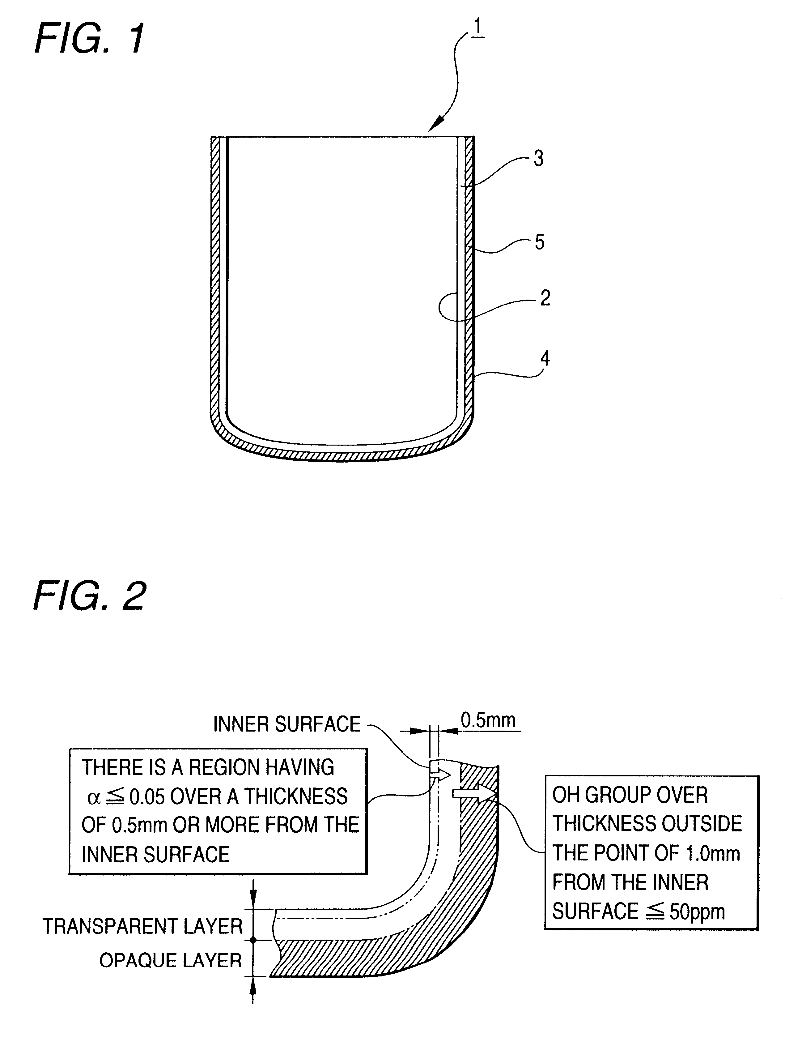
Further, when the requirement is not satisfied that the OH group concentration is 100 ppm or less over the entire periphery beyond a thickness of at least 1.0 mm from the inner surface of the silica glass crucible, the deformation of the entire silica glass crucible 1 cannot be inhibited.
Referring to the former solution, it is difficult to remove impurities or structural water completely.
Secondly, unstable oxygen is taken into and fixed in the glass network structure or stabilized as OH group.
According to the inventor's experiment, it was confirmed that this method certainly gives solution to the problem of expansion of bubbles in the silica glass crucible but is subject to considerable partial erosion of the inner surface of the silica glass crucible during the withdrawal of single crystal resulting in the drop of the percent conversion to single crystal.
In other words, when the silica glass crucible which has once been cooled is subjected to heat treatment in the following hydrogen atmosphere, impurity-containing areas scattered on the inner surface of the silica glass crucible are eroded by hydrogen, causing numerous invisible micro-cracks to occur all over the inner surface of the silica glass crucible.
Moreover, since the supply of hydrogen gas is initiated after the elapse of time t corresponding to 40% of the total arc fusion time T, the high temperature viscosity of silica glass constituting the crucible cannot be deteriorated, making it possible to obtain a silica glass crucible which can be used over an extended period of time.
The resulting crucible undergoes deformation during the withdrawal of single crystal and thus cannot be used over an extended period of time.
Further, the supply of hydrogen gas may not be initiated at the same time with the suspension of helium gas.

Method used


Image

  • Silica glass crucible and method of fabricating thereof
  • Silica glass crucible and method of fabricating thereof
  • Silica glass crucible and method of fabricating thereof

Examples


example 1

Conventional Example 1

Any section of the silica glass crucible thus used showed no general deformation of the transparent layer. However, numerous considerably large bubbles were observed, and some expansion of bubbles were observed. The resulting average conversion to single crystal was 85%.

example 2

Conventional Example 2

Any section of the silica glass crucible thus used showed no general deformation of the transparent layer. However, numerous considerably large bubbles were observed, and some expansion of bubbles were observed. The resulting average conversion to single crystal was 87%.

For the evaluation of expansion of bubbles, the transparent layer in the section of the silica glass crucible thus used was observed as compared with that of the unused silica glass crucible.

The silica glass crucible for withdrawing a single silicon crystal according to the present invention has little bubbles left in the transparent layer. Further, the expansion of bubbles left in the transparent layer can be inhibited, making it possible to prevent the bubbles in the transparent layer from entering into the molded silicon during the withdrawal of a single silicon crystal. In this arrangement, the single silicon crystal thus withdrawn from the silica glass crucible undergoes no dislocation due ...


PUM

PropertyMeasurementUnit
thicknessaaaaaaaaaa
thicknessaaaaaaaaaa
thicknessaaaaaaaaaa

Abstract

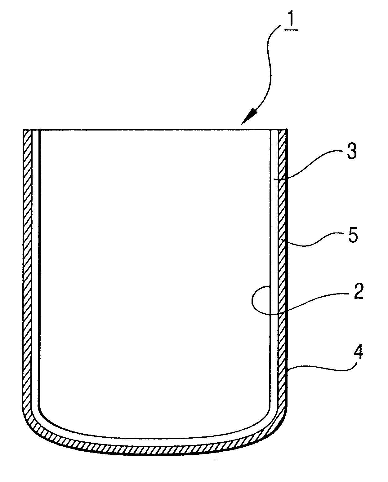
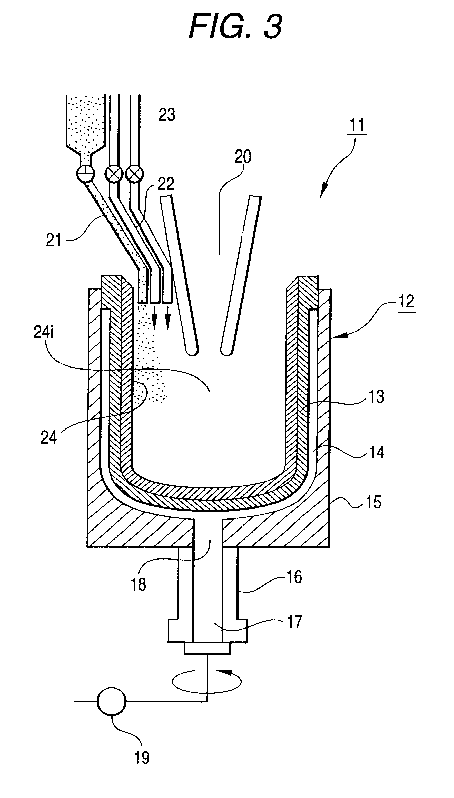
A silica glass crucible 1 having alpha of 0.05 or less over a thickness of 0.5 mm or more from the inner surface of the silica glass crucible, alpha being obtained by dividing the fluorescent intensity integrated over a wavelength range of 4,000 cm<-1 >and 4,100 cm<-1 >by the fluorescent intensity integrated at a wavelength of 800 cm<-1 >where an SiO peak appears as determined by subjecting a section of the thickness of the silica glass crucible to laser Raman spectroscopy involving excitation by laser beam of 514 nm, and an OH group concentration of 100 ppm or less over the entire periphery beyond a thickness of at least 1.0 mm from the inner surface of the silica glass crucible. A process for the preparation of a silica glass crucible for withdrawing single silicon crystal which comprises supplying helium gas or argon gas at least into the interior of the crucible-shaped molded product, and then initiating or continuing arc fusion before the termination of which the supply of argon gas is suspended or the supplied amount of argon gas is reduced and the supply of hydrogen gas is initiated.

Description

1. Field of the InventionThe present invention relates to a silica glass crucible and a method of fabricating thereof. More particularly, the present invention relates to a silica glass crucible capable of enhancing the yield in conversion to single crystal during the withdrawal of single silicon crystal and a process for the production thereof.2. Description of the Related ArtSingle silicon crystal to be incorporated in the substrate of semiconductor device is usually prepared by Czochralski process (Cz process). In accordance with CZ process, a silica glass crucible is loaded with polycrystalline silicon as a starting material. The silicon is then circumferentially heated so that it is fused. A hanging seed crystal is allowed to come in contact with the silicon melt, and then withdrawn therefrom.The conventional silica glass crucible is produced by vacuum fusion or the like. When the temperature of the silica glass crucible is raised during the withdrawal of single crystal, bubble...

Claims


Application Information

Patent Timeline
Patent Type & Authority Patents(United States)
IPC IPC(8): C03B19/09C03B19/00C30B15/10C30B15/00C03B20/00C30B29/06H01L21/02
CPCC03B19/095C30B15/10Y10T428/131Y02P40/57C03B20/00H01L21/02C30B15/00
Inventor MIYAO, ATSUROMISU, KIYOAKITAKARIKI, KAZUHIKOKAWAKAMI, IZUMIKITANO, KOUZOUOBATA, NAOYUKIYAMAGUCHI, HIROSHIKIMURA, FUSAKI
Owner COVALENT MATERIALS CORP
Learn More