Method and apparatus for controlling an audio signal level

a technology of audio signal and level, applied in the direction of gain control, code conversion, instruments, etc., can solve the problems of degrading audio signals, difficult to inexpensively manufacture pots, and difficult to achieve low-volume settings

Inactive Publication Date: 2004-02-17
CIRRUS LOGIC INC
View PDF4 Cites 86 Cited by
  • Summary
  • Abstract
  • Description
  • Claims
  • Application Information

AI Technical Summary

Problems solved by technology

This works well in most applications, with the disadvantage that it can be difficult to inexpensively manufacture pots which can precisely match one another for ganged use.
As a result, in modestly priced audio systems differences between channel volumes at low volume settings are often easily perceived.
Potentiometers, since they are passive devices, contribute no active noise to the signal path, but can degrade audio signals with resistor thermal noise, and discontinuity noise from, for example, a dirty wiper contact.
In some cases pots also allow electromagnetic interference to enter the audio path due to inadequate shielding.
VGAs are active devices akin to operational amplifiers and therefore inherently contribute some degree of noise.
This noise can be minimized with adequate design techniques, but this comes at additional cost due to larger signal handling transistors or increased bias current in gain stages.
Passive, potentiometer-based volume control systems are essentially distortionless.
VGAs are active amplification devices and are therefore subject to the usual set of non-ideal characteristics inherent in any active gain block that can contribute to overall distortion.
All-digital volume controls could potentially suffer from distortion due to truncation or rounding errors in the multiplication process.
The "trick" is to keep all variations in the gain control signal sufficiently gradual, e.g., with frequency components below 10 Hz, and / or small in amplitude, such that the modulation products remain unnoticeable or unobtrusive.
If, however, the potentiometer(s) is (are) operated by a stepper motor (as in the case of remote control) there is more risk that the individual stair steps of volume change will be noticeable, depending on the servo-stepper design.
The former method has the disadvantage of mechanical complexity and does not function well at very low or very high volume settings because one offset channel will hit the extreme stop point before the other(s).
The latter method has the disadvantage of requiring more pots.
Low distortion is more of a challenge for the VGA system because of the active nature of the gain-controlling amplifier circuitry.
The VGA will add some limited degree of distortion that usually increases with lower gain settings.
As discussed above, it will also add some degree of noise.
And, as will be understood, a DAC of that resolution is prohibitively expensive.
The added cost and undesirable complexity of such a setup is relatively easy to imagine.
A potentiometer is an electromechanical item that is subject to the deleterious effects of heat, moisture, dust, corrosion, vibration, and simple wear and tear.
In many consumer electronic devices, it is among the first subsystems of the product which develop problems, usually due to dirt or dust contamination.
In addition, if a motor of some sort is used to actuate the potentiometer digitally or remotely, the electromechanical complexity increases and reliability correlatively decreases.
A VGA system is relatively easily designed by an experienced circuit designer, but can be somewhat complex.
Digital implementation is fairly straightforward to an experienced digital ASIC designer but adds complexity to the DAC design.
The VGA approach can be integrated, but makes for a fairly complex analog IC function if high performance is targeted.
Concentric slip-clutch potentiometers are more costly, and pot combinations that are sealed against dust and have good inter-pot tracking are even more expensive.
When a servo operation mechanism is added, the cost goes up dramatically.
VGAs are not particularly expensive, but are more costly than op amps of similar performance ratings simply because they are sold in lower quantities.
It is clear from the above discussion that each of the currently available techniques for implementing volume control in audio systems has its disadvantages with regard to at least some of the desirable characteristics of volume control circuitry.

Method used


Image

  • Method and apparatus for controlling an audio signal level
  • Method and apparatus for controlling an audio signal level
  • Method and apparatus for controlling an audio signal level

Examples


Embodiment Construction

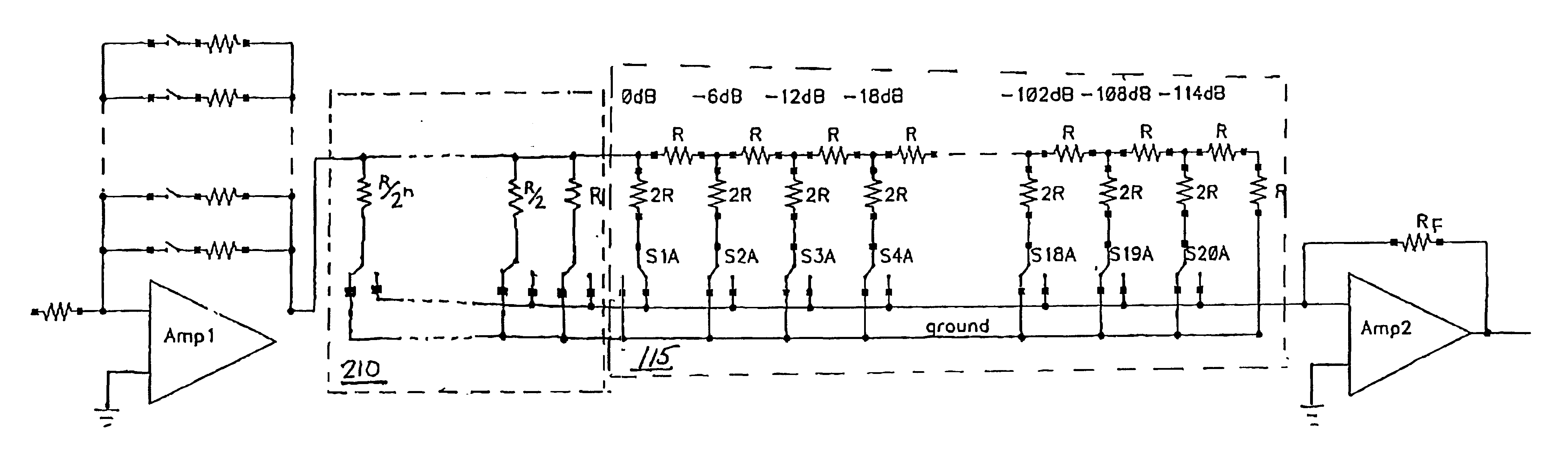
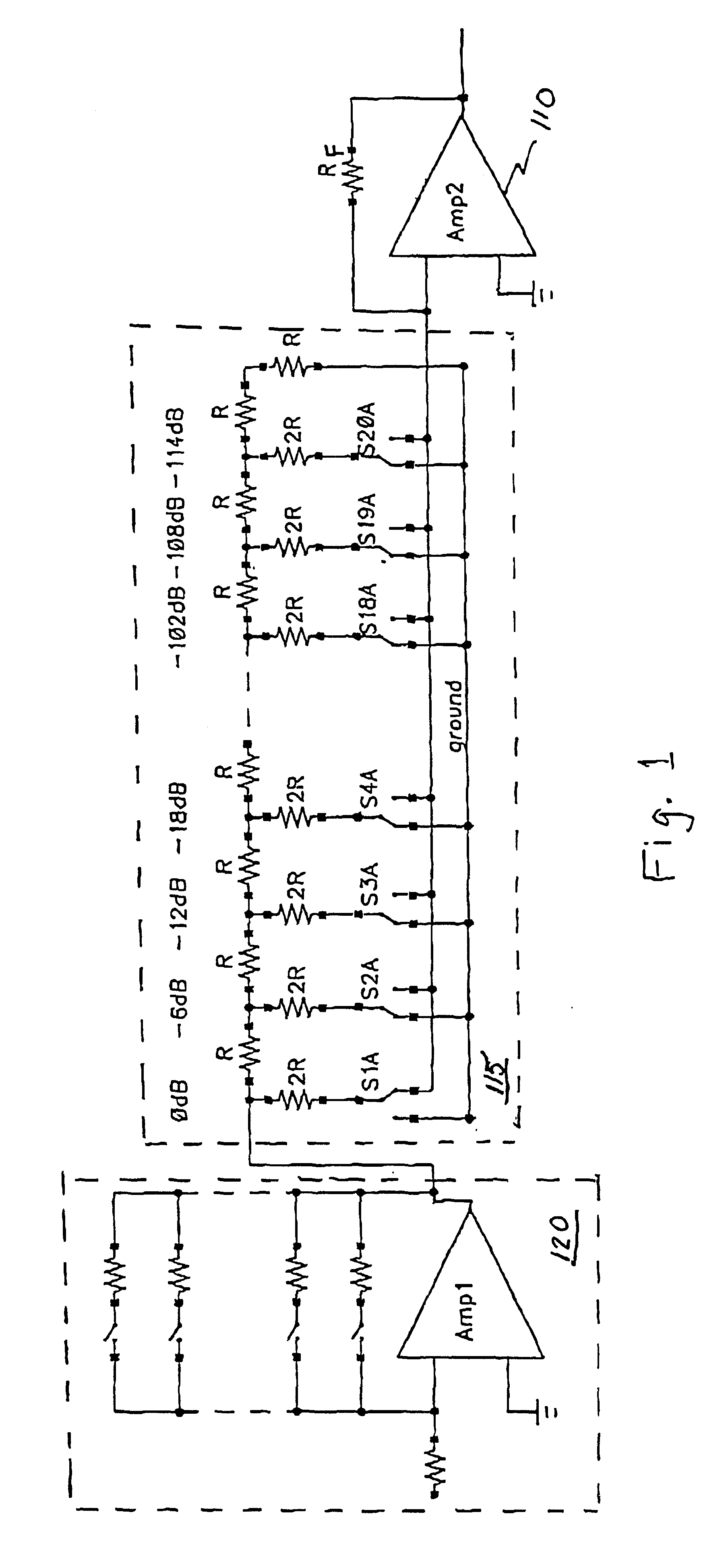
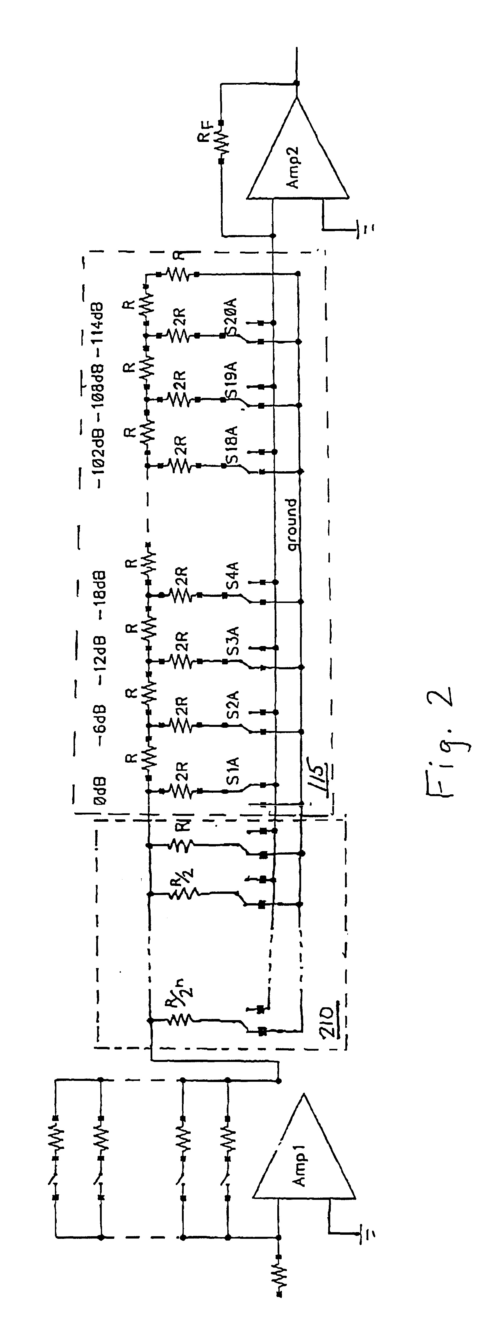
Methods and apparatus for controlling a signal level are described in U.S. patent application Ser. No. 09 / 156,262 for METHOD AND APPARATUS FOR CONTROLLING AN AUDIO SIGNAL INPUT LEVEL filed on Sep. 18, 1998, the entire disclosure of which is incorporated herein by reference for all purposes. In a specific embodiment described in that application, the invention provides a volume control circuit with a large dynamic range, cheaply implemented, with low noise based on an R-2R network. FIG. 1 shows an example of such an implementation.

The circuit of FIG. 1 takes advantage of the logarithmic characteristic of the R-2R resistor network topology to precisely attenuate an incoming analog audio signal in 6 dB steps for any number of channels. The 2R resistors are selectively switched between ground and the virtual ground represented by the input of an operational amplifier 110 following the R-2R network 115. Because the operation of the network is essentially independent of the base resistor ...


PUM


Abstract

A control circuit for controlling a level of an audio signal and transmitting the signal to an amplifier is described. The control circuit is based on an R-2R resistor network having a first plurality of resistor nodes and a parallel resistor network having a second plurality of resistor nodes. Each of the resistors in the parallel network has a value equal to one-half of the value of the preceding resistor. A plurality of switches alternately connects each of the plurality of resistor nodes to one of a plurality of low impedance nodes and a low impedance input node associated with the amplifier. Switch control circuitry selectively controls the plurality of switches to transmit the audio signal to the low impedance input node.

Description

1. Field of the InventionThe present invention relates to techniques for controlling the level of a signal. More specifically, the present invention provides methods and apparatus for controlling the level of a signal of amplifiers.2. Description of the Prior ArtVirtually all audio amplification systems require a means of controlling the overall gain of the signal path. Such systems are described in described in U.S. Pat. No. 5,777,512 for METHOD AND APPARATUS FOR OVERSAMPLED, NOISE-SHAPING, MIXED-SIGNAL PROCESSING issued on Jul. 7, 1998, the entire disclosure of which is incorporated herein by reference for all purposes as well as in U.S. patent application Ser. No. 09 / 156,262 for METHOD AND APPARATUS FOR CONTROLLING AN AUDIO SIGNAL INPUT LEVEL filed on Sep. 18, 1998, the entire disclosure of which is incorporated herein by reference for all purposes.Such gain control enables the system engineer to optimize signal levels to fit the dynamic range of the system and allows end-users t...

Claims


Application Information

Patent Timeline
Patent Type & Authority Patents(United States)
IPC IPC(8): H03G1/00
CPCH03G1/0088
Inventor DELANO, CARY L.
Owner CIRRUS LOGIC INC
Why Eureka
Try Eureka