

Method of making material alloy for iron-based rare earth magnet
a rare earth magnet and alloy technology, applied in the field of making material alloys for iron-based rare earth magnets, can solve the problems of high remanence b.sub.r of 0.5 t or more, high cost of sm-co type magnets, and high cost of producing nd--fe-b type magnets, so as to increase the thermal resistance of alloys and improve the loop squareness of demagnetization curves.
Inactive Publication Date: 2004-02-24
SUMITOMO SPECIAL METAL CO LTD
View PDF10 Cites 59 Cited by
- Summary
- Abstract
- Description
- Claims
- Application Information
AI Technical Summary
Benefits of technology
"The present invention provides methods for making an iron-based rare earth magnet with a uniform microcrystalline structure that exhibits high performance. The methods involve rapidly cooling and solidifying an iron-based rare earth material alloy using a chill roller and a guide, followed by a heat treatment step to form a structure with three or more crystalline phases, including at least R.sub.2 Fe.sub.14 B and .alpha.-Fe phases, and a bonded magnet can also be produced using the powder of the rapidly solidified alloy. The methods provide improved control over the microstructure of the magnet, leading to better performance and reproducibility."
Problems solved by technology
However, the hard ferrite magnets cannot achieve the high remanence B.sub.r of 0.5 T or more.
However, the Sm--Co type magnet is expensive, because Sm and Co are both expensive materials.
Nevertheless, it is still expensive to produce the Nd--Fe--B type magnet.
Furthermore, a powder metallurgical process normally requires a relatively large number of manufacturing and processing steps by its nature.
However, in producing a nanocomposite magnet by a melt quenching process, the microcrystalline structure of a rapidly solidified alloy is seriously affected by how a melt of a material alloy contact the surface of a chill roller, and the resultant magnet properties may sometimes deteriorate.
Particularly when a nanocomposite magnet was be made by a strip casting process, the present inventors found it very difficult to obtain a rapidly solidified alloy having the desired micro crystalline structure uniformly and with good reproducibility.
In that case, the melt flow was obstructed by the oxide film, and the rapid cooling process could not be carried out uniformly enough.
Method used
View moreImage
Smart ImageViewing Examples

Examples
example 2
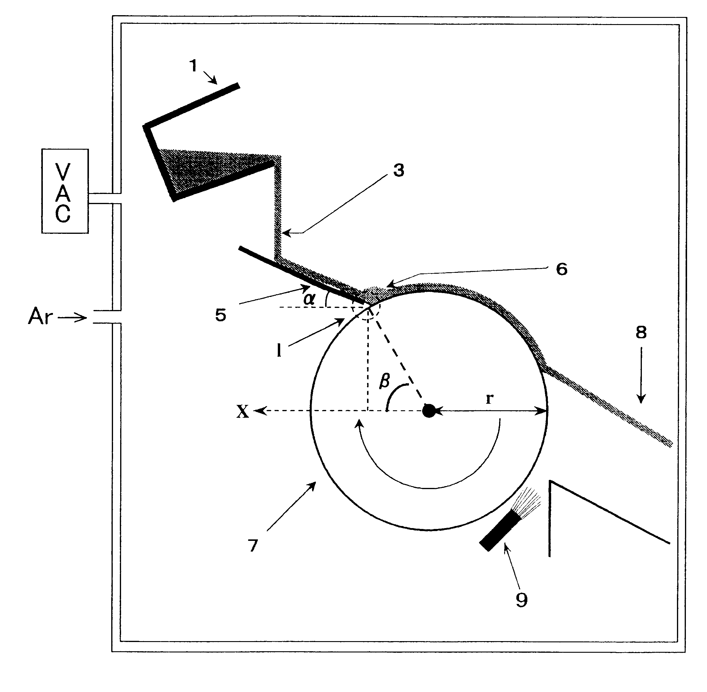
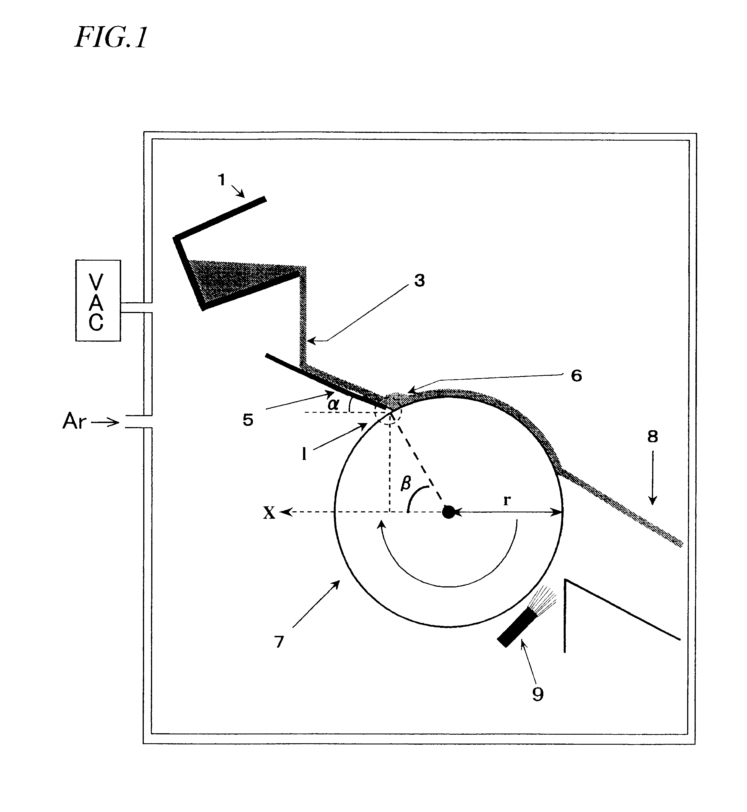
An alloy was made from a material alloy having the composition No. 3 shown in Table 1 using the strip caster shown in FIG. 1 under the same conditions as those of the first example except the shoot angle a and the concentration of oxygen in the melt. The following Table 3 shows whether or not each of various shoot angle / oxygen concentration combinations allowed a puddle of the melt to be formed on the roller surface constantly enough to obtain the desired quenched alloy (SC alloy):
As can be seen from the results of these examples, where the melt has an oxygen concentration of about 2,000 ppm or less, the shoot angle .alpha. is preferably about 10 degrees to about 50 degrees, more preferably from about 20 degrees to about 30 degrees.
Login to View More PUM
| Property | Measurement | Unit |
|---|---|---|
| average crystal grain size | aaaaa | aaaaa |
| average crystal grain size | aaaaa | aaaaa |
| average crystal grain size | aaaaa | aaaaa |
Abstract
A melt of an iron-based rare earth material alloy, represented by (Fe1-mTm)100-x-y-zQxRyMz, is prepared, wherein T is Co and / or Ni; Q is B and / or C; R is selected from Y (yttrium) and the rare earth elements; M is selected from Al, Si, Ti, V, Cr, Mn, Cu, Zn, Ga, Zr, Nb, Mo, Ag, Hf, Ta, W, Pt, Au and Pb; 10<=x<=30 at %; 2%<=y<10 at %; 0<=z<=10 at % and 0<=m<=0.5. The melt is fed onto a guide to form a flow of the melt thereon and move the melt onto a melt / chill roller contact region, where the melt is rapidly cooled by the chill roller to make a rapidly solidified alloy. An oxygen concentration of the melt yet to be fed onto the guide is controlled at about 3,000 ppm or less in mass percentage.
Description
The present invention relates to a method of making a material alloy for an iron-based rare earth magnet, for use in, for example, motors and actuators of various types.Recently, it has become more and more necessary to further improve the performance of, and further reduce the size and weight of, consumer electronic appliances, office automation appliances and various other types of electric equipment. For these purposes, a permanent magnet for use in each of these appliances is required to maximize its performance to weight ratio when operated as a magnetic circuit. For example, a permanent magnet with a remanence B.sub.r of 0.5 T or more is now in high demand. Hard ferrite magnets have been used widely because magnets of this type are relatively inexpensive. However, the hard ferrite magnets cannot achieve the high remanence B.sub.r of 0.5 T or more.An Sm--Co type magnet, produced by a powder metallurgical process, is currently known as a typical permanent magnet that achieves th...
Claims
Login to View More Application Information
Patent Timeline
 Patent Type & AuthorityPatents(United States)
IPC IPC(8): B22D11/06C22C38/00C22C1/04H01F1/057H01F1/058H01F1/032
CPCB22D11/0611B82Y25/00C22C1/0441C22C38/002C22C38/005H01F1/0571H01F1/0578H01F1/0579H01F1/058H01F1/053
InventorKANEKIYO, HIROKAZUHIROSAWA, SATOSHI
OwnerSUMITOMO SPECIAL METAL CO LTD