
System and method for performing thin film deposition or chemical treatment using an energetic flux of neutral reactive molecular fragments, atoms or radicals

a technology of neutral reactive molecular fragments and energetic fluxes, applied in vacuum evaporation coatings, electrolysis components, coatings, etc., can solve problems such as iad that is too violent and damaging, and practitioners typically fear two aspects of iad, and significant momentum-transfer damage may occur

Inactive Publication Date: 2004-04-20
4WAVE
View PDF2 Cites 12 Cited by
  • Summary
  • Abstract
  • Description
  • Claims
  • Application Information

AI Technical Summary

Benefits of technology

In accordance with further aspects, a controller may vary the value of the bias applied to the at least one target, and thereby vary the kinetic energy of the neutral chemically reactive molecular fragments, atoms or radicals intercepted by the substrate. In one embodiment, the controller continuously varies the value of the bias applied to the at least one target, and thereby continuously varies the kinetic energy of the neutral chemically reactive molecular fragments, atoms or radicals intercepted by the substrate over a range from 1-30 eV or higher. The controller can also optionally vary an angle of the substrate such that an arrival angle of the neutral chemically reactive molecular fragments, atoms or radicals intercepted at the exposed surface of the substrate varies from a substantially normal angle of incidence to a substantially grazing angle of incidence. An electron source may also be disposed in the chamber to provide electrons that neutralize accumulated ion-charge build-up on the target.
In a further embodiment, first and second targets are disposed in the chamber. In this embodiment, chemically reactive molecular ions accelerated toward the first target cause atoms from the surface of the first target to be sputtered away from the first target, and chemically reactive molecular ions accelerated toward the second target cause atoms from the surface of the second target to be sputtered away from the second target. Portions of the atoms sputtered from the surfaces of the first and second targets collect upon the exposed surface of the substrate with neutral chemically reactive molecular fragments, atoms or radicals scattered from the first and second targets and intercepted by the substrate. A thin film formed on the exposed surface of the substrate includes a chemical compound or alloy resulting from reaction of the atoms sputtered from the surfaces of the first and second targets with the neutral chemically reactive molecular fragments, atoms or radicals scattered from the first and second targets and intercepted by the substrate. A controller may vary or control properties of the thin film by controlling arrival rates at the exposed surface of the substrate of the atoms sputtered from the surfaces of the first and second targets and the neutral chemically reactive molecular fragments, atoms or radicals scattered from the first and second targets.

Problems solved by technology

Many practitioners of thin film deposition art consider IAD too violent and damaging when applied to highly sensitive, damage-prone substrates.
With respect to these devices, practitioners typically fear two aspects of IAD.
In this higher (25 eV to 100 eV per ion) kinetic energy range, it is justifiably expected that significant momentum-transfer damage may occur, either by lattice disruption, intermixing or sputtering.
Regarding electric charge damage to sensitive substrates, the arriving ions may build up a macroscopic positive charge on the surface of an insulating substrate, which can lead to dielectric breakdown with attendant local heating or lattice disruption.
Most of this energy is dissipated to the surface atoms, potentially causing lattice disruption and / or local heating.
Therefore the concept of using these reactive neutrals produced in the gas phase in place of IAD ions fails.
The atom beam spot size was .about.1 mm, and scaling up appears difficult and expensive.
Such a method provides inefficient means of dissociating molecular ions into atoms, and, in the case of using a pre-selected atomic ion beam such as N.sup.+ or O.sup.+, resonant charge exchange neutralization would be difficult owing to the impracticality of producing sufficient density of neutral N or O atoms in the charge-exchange cell while keeping the overall pressure low enough to allow passage of the fast ions / atoms out the exit of the cell.
The NABS requires large Kaufman sources that are expensive, the grids wear and become electrically shorted by sputter debris and the ion current output decreases sharply as a function of ion beam energy below 250 eV due to space charge limitations within the grids.
Also, in a high-rate, mass-production deposition apparatus, the substrate side of the metal membrane might become coated with stray coating intended for the substrate, thus potentially "poisoning" the inner surface of the membrane for either surface accumulation of O atoms or their desorption, rendering the device impractical in this application.

Method used


Image

  • System and method for performing thin film deposition or chemical treatment using an energetic flux of neutral reactive molecular fragments, atoms or radicals
  • System and method for performing thin film deposition or chemical treatment using an energetic flux of neutral reactive molecular fragments, atoms or radicals
  • System and method for performing thin film deposition or chemical treatment using an energetic flux of neutral reactive molecular fragments, atoms or radicals

Examples


Embodiment Construction

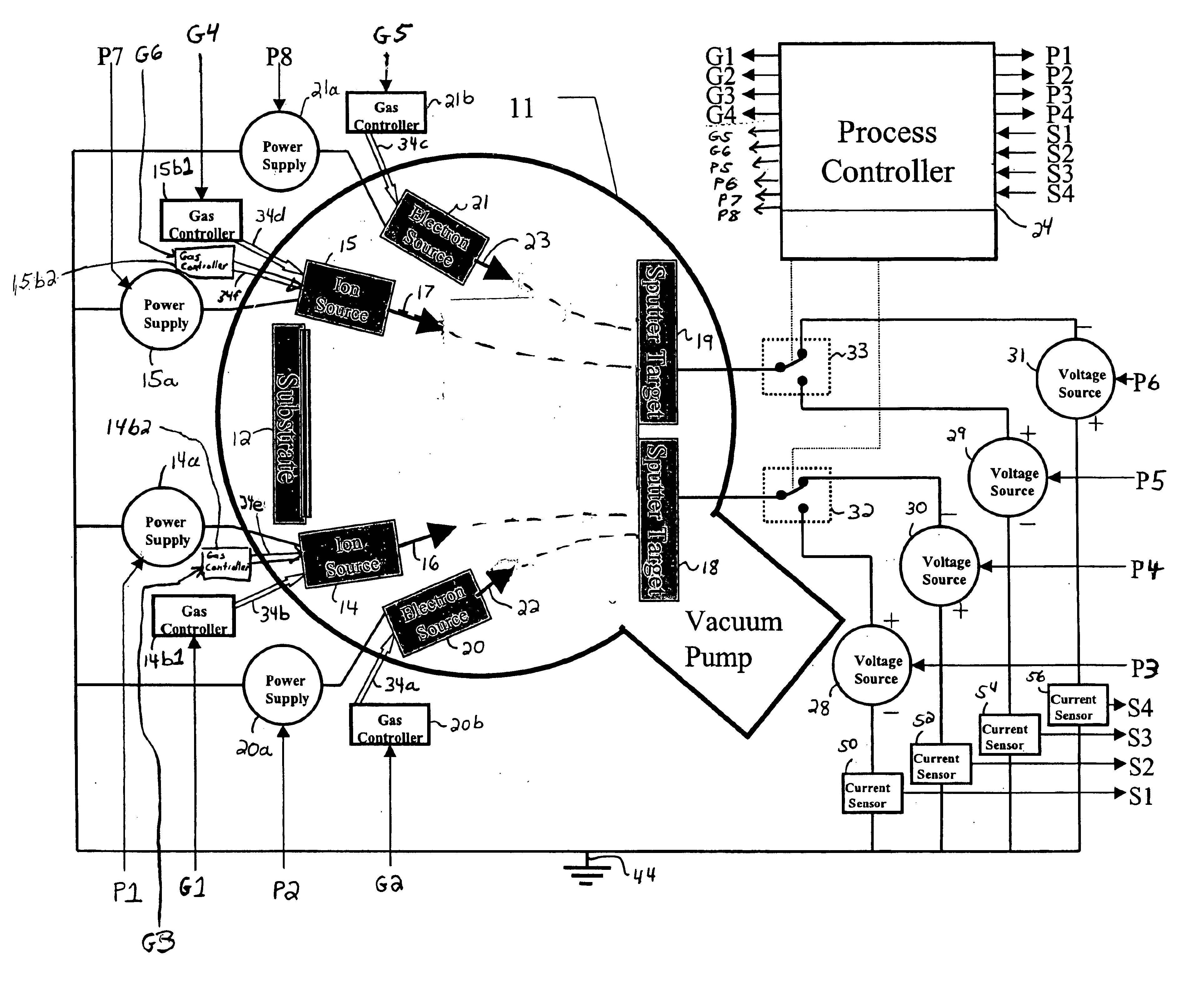
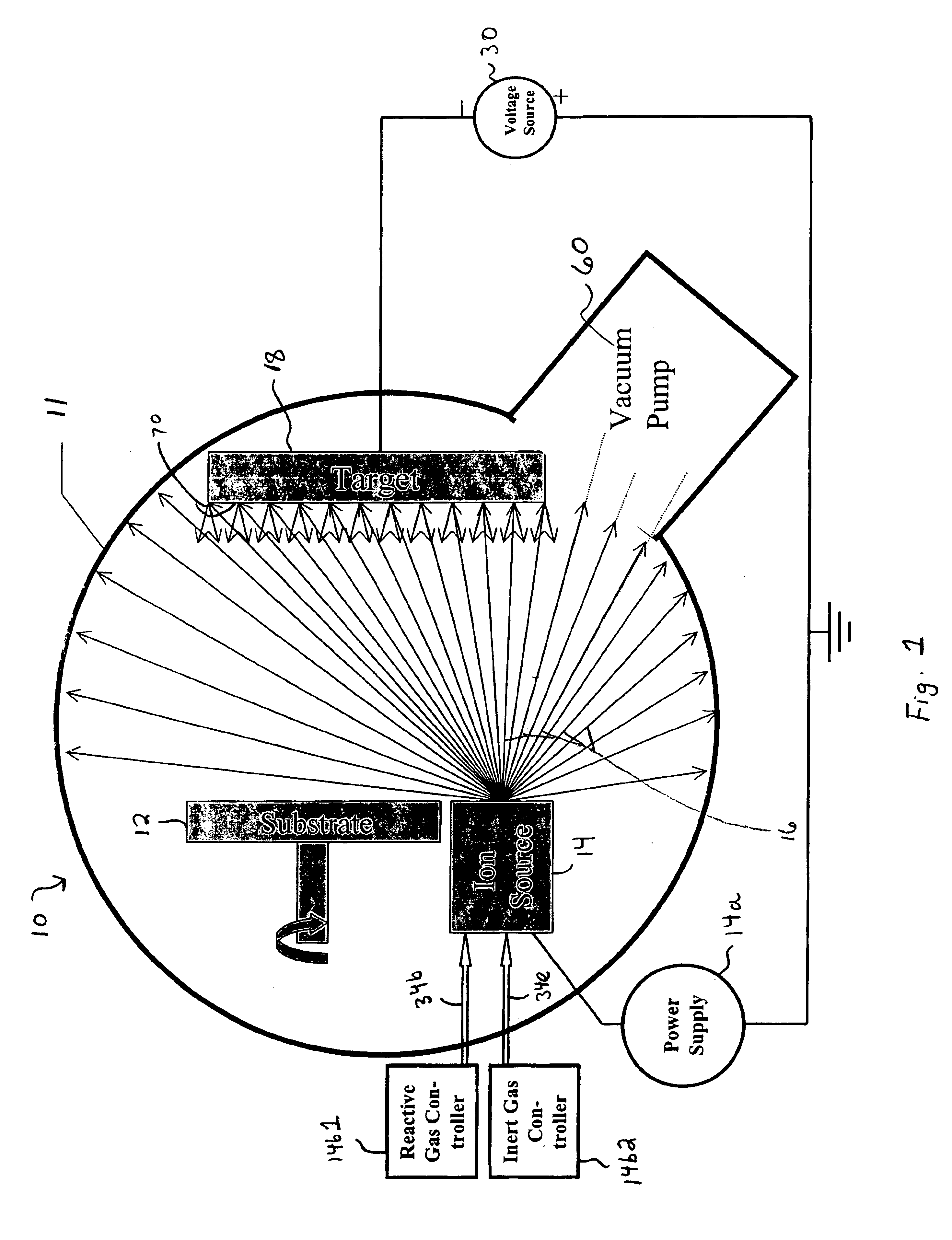
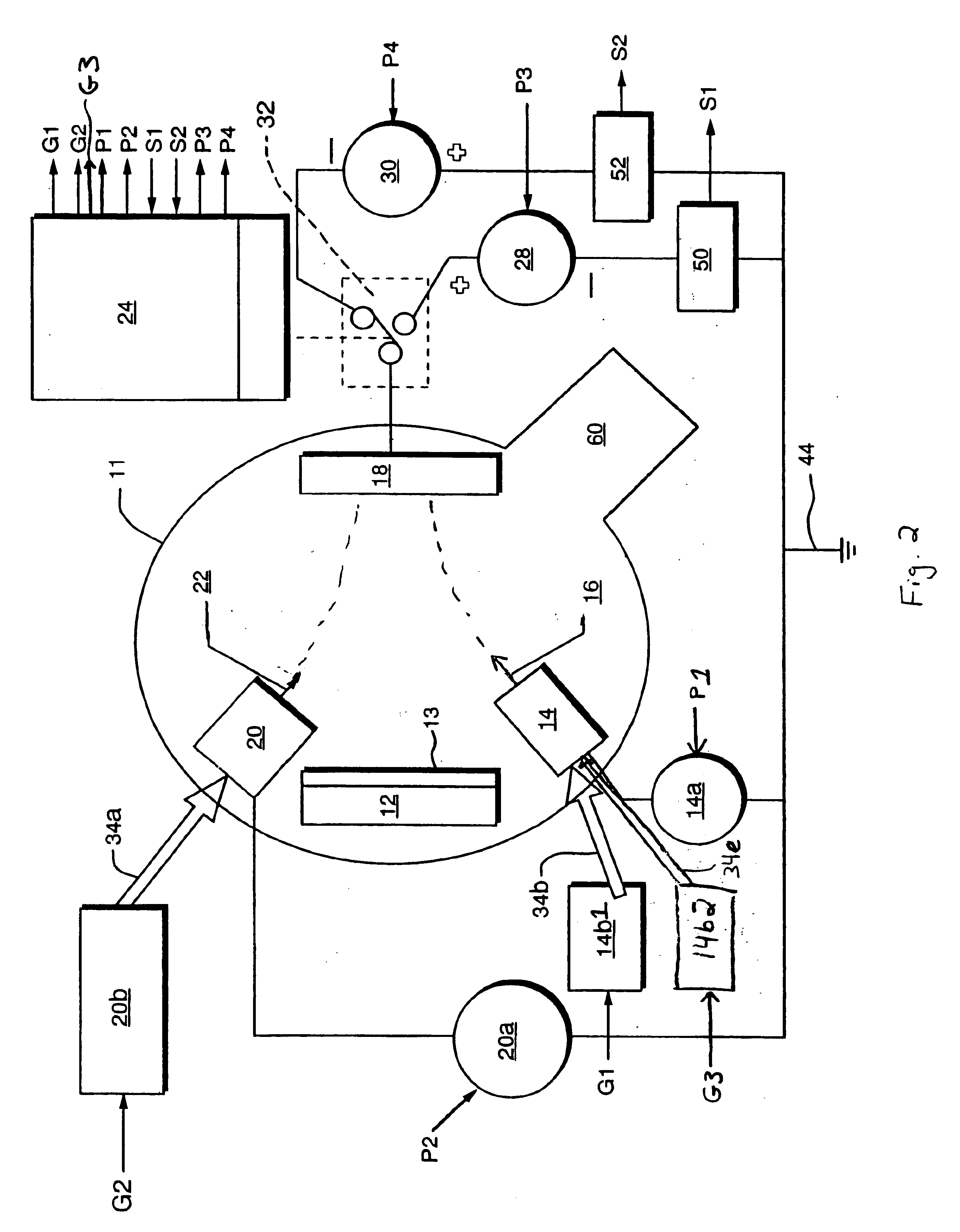
There is shown in FIGS. 1-2, a system 10 for forming a chemically reacted layer 13 on or near the surface of a substrate 12. Reactive gas controller 14b1 provides a chemically reactive molecular gas 34b to an ion source 14, which generates a divergent ion current 16 directed at the target 18. The ion current 16 contains at least one species of chemically reactive molecular ion, and the target 18 is disposed in a chamber 11 having a partial vacuum in the range of 10.sup.-2 to 10.sup.-5 Torr. A voltage source 30 applies a bias to the target 18 such that chemically reactive molecular ions from the ion source 14 are accelerated toward the target 18 with sufficient kinetic energy to dissociate at least some of the chemically reactive molecular ions by collision with the surface of the target 18 to form a population 70 of neutral chemically reactive molecular fragments, atoms or radicals at least some of which scatter away from the surface of the target 18 and into the chamber 11. At leas...


PUM

PropertyMeasurementUnit
Energyaaaaaaaaaa
Thicknessaaaaaaaaaa
Angleaaaaaaaaaa

Abstract

A system and method for forming a chemically reacted layer proximate an exposed surface of a substrate is disclosed. A gas supply provides a chemically reactive molecular gas to an ion source that generates a divergent ion current directed at a target. The ion current contains at least one species of chemically reactive molecular ion, and the target is disposed in a chamber having a partial vacuum. A voltage source applies a bias to the target such that chemically reactive molecular ions from the ion source are accelerated toward the target with sufficient kinetic energy to dissociate at least some of the chemically reactive molecular ions by collision with the surface of the target.

Description

FIELD OF INVENTIONThe present invention is directed generally to novel systems and methods for performing thin film deposition or chemical treatment of substrates, and to optical devices manufactured using such systems and methods.BACKGROUND OF THE INVENTIONU.S. Pat. No. 6,402,904 (the '904 patent) and U.S. patent application Ser. No. 09 / 810,688 filed Mar. 16, 2001, entitled "System and Method for Performing Sputter Deposition Using Ion Sources, Targets and a Substrate Arranged About the Faces of a Cube" (also incorporated herein by reference) (the '688 application) disclose systems and methods for ion sputter deposition of thin films on a substrate which involve directing ions from at least one plasma ion source generally towards at least one sputter target, each target having its own associated ion source. In operation, negative voltages applied to the target(s) attract ions from the plasma and accelerate the ions toward the target to sufficient kinetic energies (50 to 5000 eV) to...

Claims


Application Information

Patent Timeline
IPC IPC(8): C23C14/46C23C14/54H01J37/34H01J37/32H01J37/317
CPCC23C14/46C23C14/54H01J37/3178H01J37/3233H01J37/34
Inventor BALDWIN, DAVID ALANHYLTON, TODD LANIER
Owner 4WAVE
Learn More