Method and apparatus for manufacturing ceramic-based composite member

a ceramic-based composite and airtight technology, applied in the direction of surface layering apparatus, machine/engine, manufacturing tools, etc., can solve the problems of high density, heavy weight, and defects in materials

Inactive Publication Date: 2004-04-20
IHI CORP
View PDF21 Cites 9 Cited by
  • Summary
  • Abstract
  • Description
  • Claims
  • Application Information

AI Technical Summary

Benefits of technology

The method of the present invention is characterized in that after an SiC matrix phase is produced on the surface of a fiber fabric, the fabric is processed in a pressurized infiltration process. The SiC matrix phase can be created by, for example, a CVI process, as a crackless, dense matrix formed around ceramic fibers. Next, an organic silicon polymer is pressurized in the direction of practical operating pressure of the fiber fabric and pressure-infiltrated through a PIP process, thereby the matrix is formed preferentially in gaps in the matrix phase, gaps after the CVI process are filled, and airtightness of the member can be increased.
Because there are microscopic cracks in the matrix created by the PIP process, bonding forces between ceramic fibers are weak. Therefore, as disclosed in the Japanese patent application No. 019416 / 1999 (unpublished), as the member is subjected to the PIP process in addition to the CVI process, the modulus of elasticity can be reduced more than that of a conventional CMC produced only by the CVI process, so thermal stresses are reduced and resistance to thermal shock can be greatly improved, as verified through experiments.
In this way, a matrix is formed preferentially in gaps penetrating the composite member, and airtightness can be increased in a short period.
In this configuration according to the invention, the fiber fabric (11) with the SiC matrix phase formed on the surface using holding device (12) is kept water-tight, and the organic silicon polymer (8) is pressurized in the direction of pressurizing the fiber fabric during use, and is fed, therefore, by adjusting the pressure the organic silicon polymer can be fed into the fiber fabric at a substantially uniform pressure. In addition, because the organic silicon polymer can be pressurized in the direction of the operating pressure of the fabric and infiltrated into the fabric under pressure, the matrix is created preferentially in gaps in the matrix phase, so that gaps remaining after CVI and PIP processes can be filled, thus the airtightness of the fabric can be increased. Furthermore, degassing device (16) can remove the part of the organic silicon polymer that contains a lot of gas bubbles, and as a result, the uniform organic silicon polymer without bubbles contained can be fed preferentially into gaps in the matrix phase, and a highly airtight matrix can be produced.

Problems solved by technology

However, these materials have such defects as high density, heavy weight, low strength at a high temperature, and short life of coating.
However, conventional CMCs were problematic in that airtightness could not be retained and resistance to a heat shock was poor.
More explicitly, with a conventional CMC, ceramic fibers were formed into a predetermined shape, and a matrix was created in gaps between fibers by the so-called CVI (Chemical Vapor Infiltration) process, and to completely fill gaps between fibers with the matrix produced in this CVI process, an impractically long time (for instance, more than one year) was required, which was very difficult.
Also, to increase the airtightness of CMC itself, the PIP (Polymer Impregnate and Pyrolysis Method) process in which components made of ceramic fibers are only dipped in a molten material polymer is effective, however, the cycle of impregnating and heating must be repeated many times (for instance, more than 40 times), so efficiency is poor.
However the method needs some huge apparatuses such as dies.
Because there are microscopic cracks in the matrix created by the PIP process, bonding forces between ceramic fibers are weak.

Method used


Image

  • Method and apparatus for manufacturing ceramic-based composite member
  • Method and apparatus for manufacturing ceramic-based composite member
  • Method and apparatus for manufacturing ceramic-based composite member

Examples


embodiments

Embodiments of the present invention are described below.

1. Method for Manufacturing Chamber

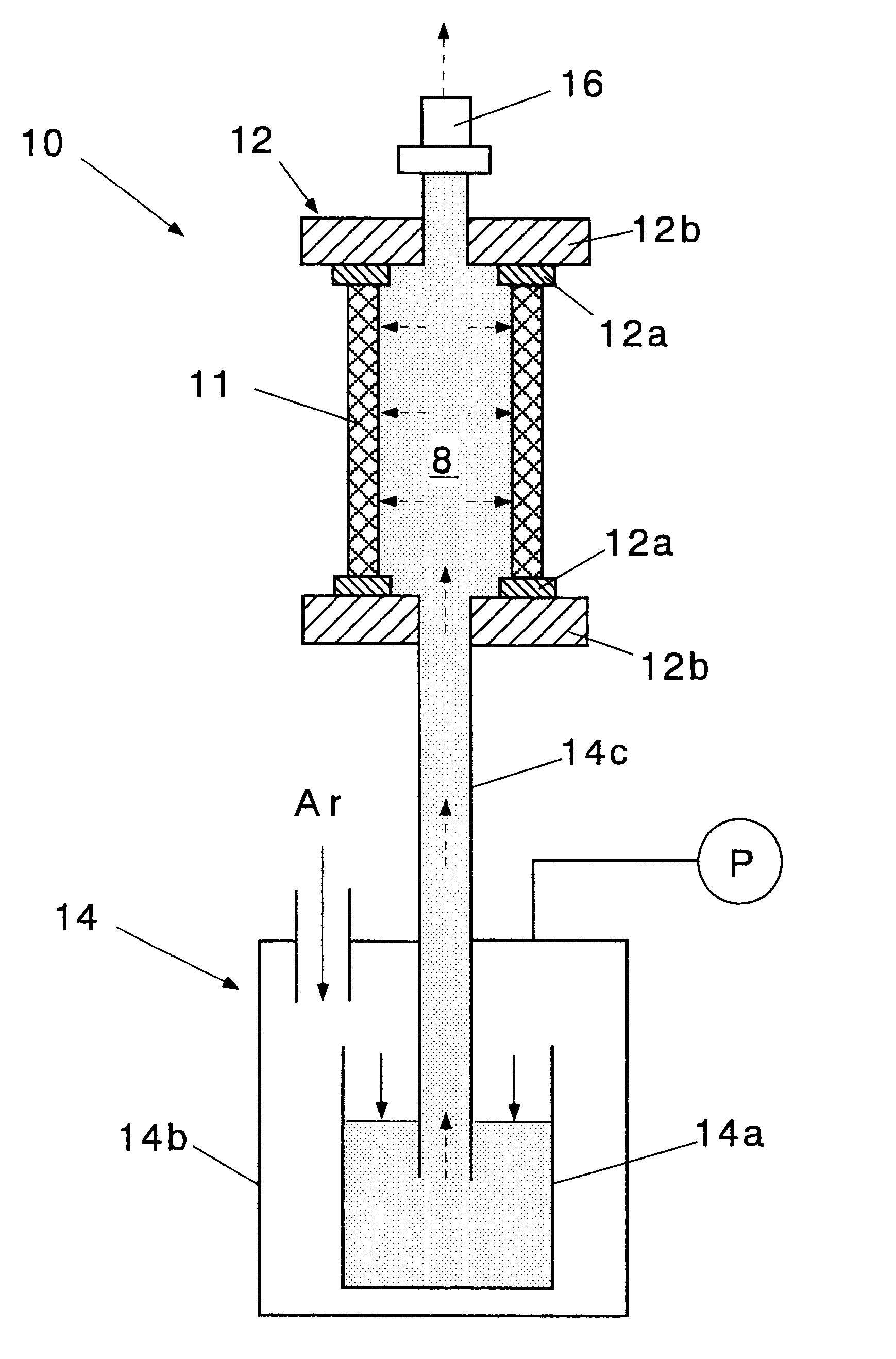
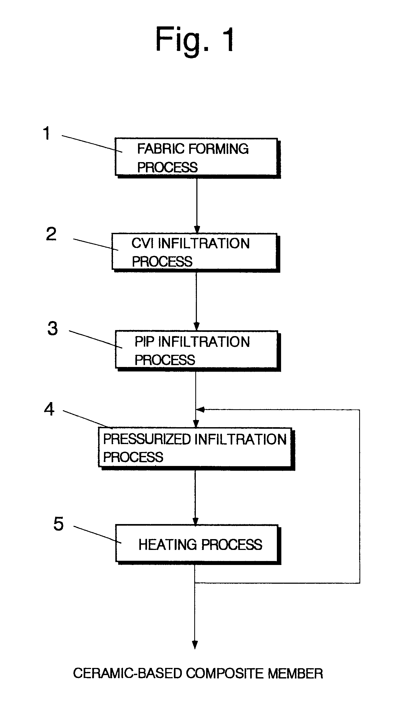
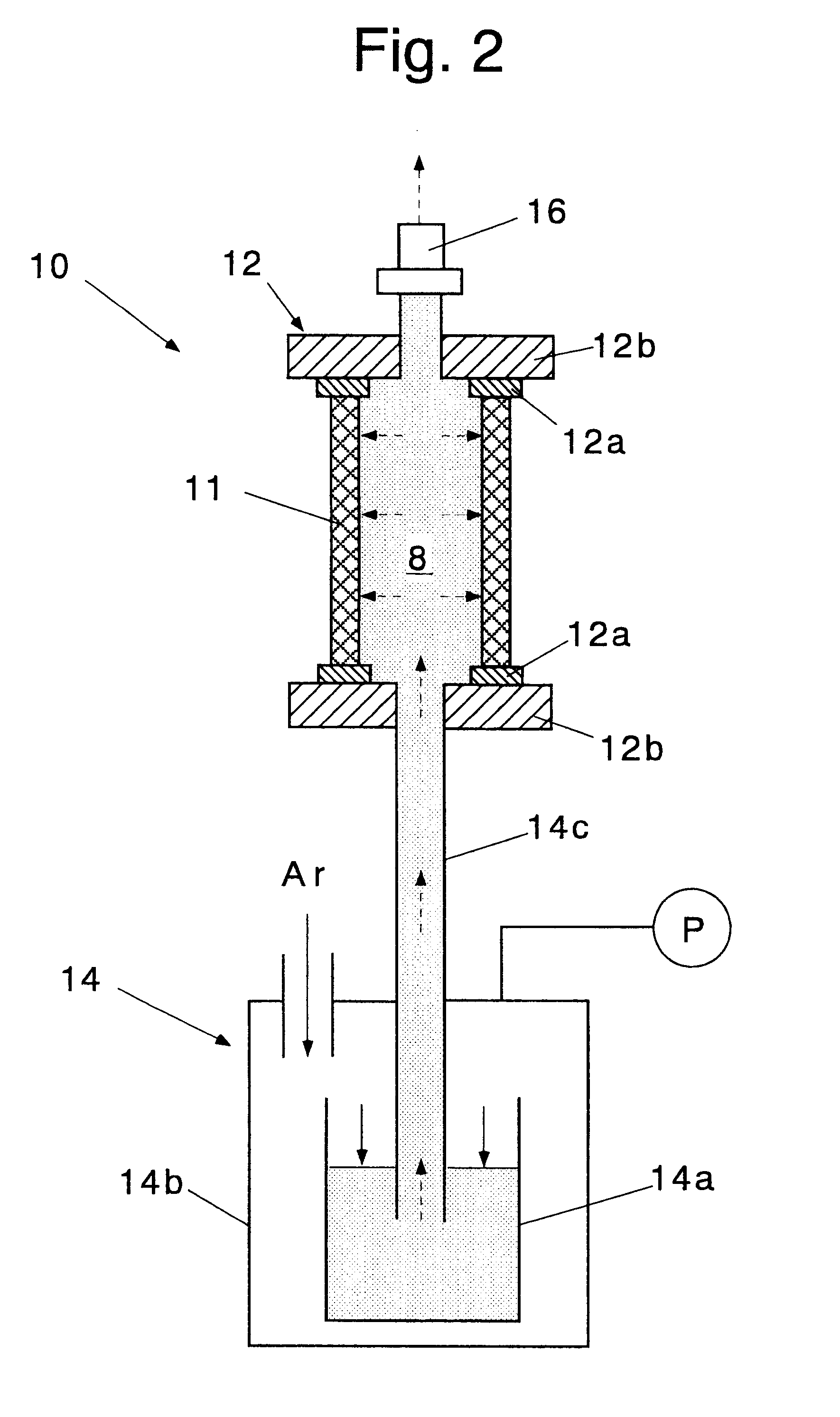
SiC / SiC chambers were manufactured according to the manufacturing method shown in FIG. 1. Tyranno Lox-M fibers supplied from Ube Industries, Ltd. were used as SiC fibers for the chamber. The fibers were braided on a mandrel, and SiC matrix was infiltrated. To infiltrate the matrix, CVI infiltration process 2, ordinary PIP treatment process 3, and above-mentioned pressurized infiltration process 4 were combined.

2. Leakage Test

A leakage test was performed at 0.7 MPa. A chamber was submerged in water, pressurized with N.sub.2 gas, and gas passed through the chamber was collected and measured to determine the leakage rate. A seal was provided between the chamber and the chamber throat.

FIG. 3 shows results of the leakage test. Even after work was CVI-processed in CVI infiltration process 2 for about one month, there were voids at about 20% of the total volume, and total measured leakage rate corre...


PUM

PropertyMeasurementUnit
temperatureaaaaaaaaaa
thicknessaaaaaaaaaa
temperatureaaaaaaaaaa

Abstract

An organic silicon polymer is infiltrated and charged into gaps in a matrix phase of a formed fiber fabric, and its airtightness is increased by (a) CVI infiltration process 2 for forming the SIC matrix phase on the surface of the fiber fabric formed, (b) pressurized infiltrations process 4 for pressurizing the organic silicon polymer in the direction operating pressure is applied to the fiber fabric during use and infiltrating the organic silicon polymer into gaps in the aforementioned matrix phase, and (c) heating process 5 for heating the infiltrated fiber fabric at a high temperature. Thus, airtightness can be increased quickly, and fired work can be applied practically even to thrust chambers etc.

Description

This application claims priority on Japanese Patent Application Number 251410 / 1999, filed Sep. 6, 1999, the entire disclosure of which is incorporated herein by reference.1. Technical Field of the InventionThe present invention relates to a method and an apparatus for manufacturing a highly airtight, ceramic-based composite member.2. Prior ArtThe thrust chamber of a rocket engine using a propellant such as NTO / N.sub.2 H.sub.4 and NTO / MMH is required to be capable of operating at a high temperature that provides higher engine performance. For this purpose, niobium alloys with a coating that can operate at a temperature of about 1,500.degree. C. have been used conventionally as the chamber material for many rocket engines. However, these materials have such defects as high density, heavy weight, low strength at a high temperature, and short life of coating.On the other hand, ceramics can resist heat, but are brittle, therefore the ceramic matrix composite (CMC) was developed by reinfo...

Claims


Application Information

Patent Timeline
Patent Type & Authority Patents(United States)
IPC IPC(8): B28B13/00B28B13/02B28B19/00C04B35/80C04B35/571C04B35/565C23C16/04F02K9/97F02K9/00F02K9/62
CPCB28B13/021B28B19/0092C04B35/571C04B35/806C23C16/045F02K9/62F02K9/974F05D2300/2261F05D2300/224F05D2300/603F05D2300/615C04B35/80
Inventor MURATA, HIROSHIGESHIODA, MUNEYOSHINAKAMURA, TAKESHI
Owner IHI CORP
Why Eureka
Try Eureka