
Apparatus for delivering air-borne substances

a technology of air-borne substances and apparatuses, which is applied in the direction of medical atomisers, inhalators, etc., can solve the problems of particle loss, inefficient aerosol delivery, and high cost of current mdi aerosol generators, and achieve the effect of maximizing the placement density

Inactive Publication Date: 2004-04-27
CHARLES RIVER LAB INC
View PDF19 Cites 23 Cited by
  • Summary
  • Abstract
  • Description
  • Claims
  • Application Information

AI Technical Summary

Benefits of technology

The numerous objects and advantages of the present invention may be better understood by those skilled in the art by reference to the accompanying non-scale figures, in which:
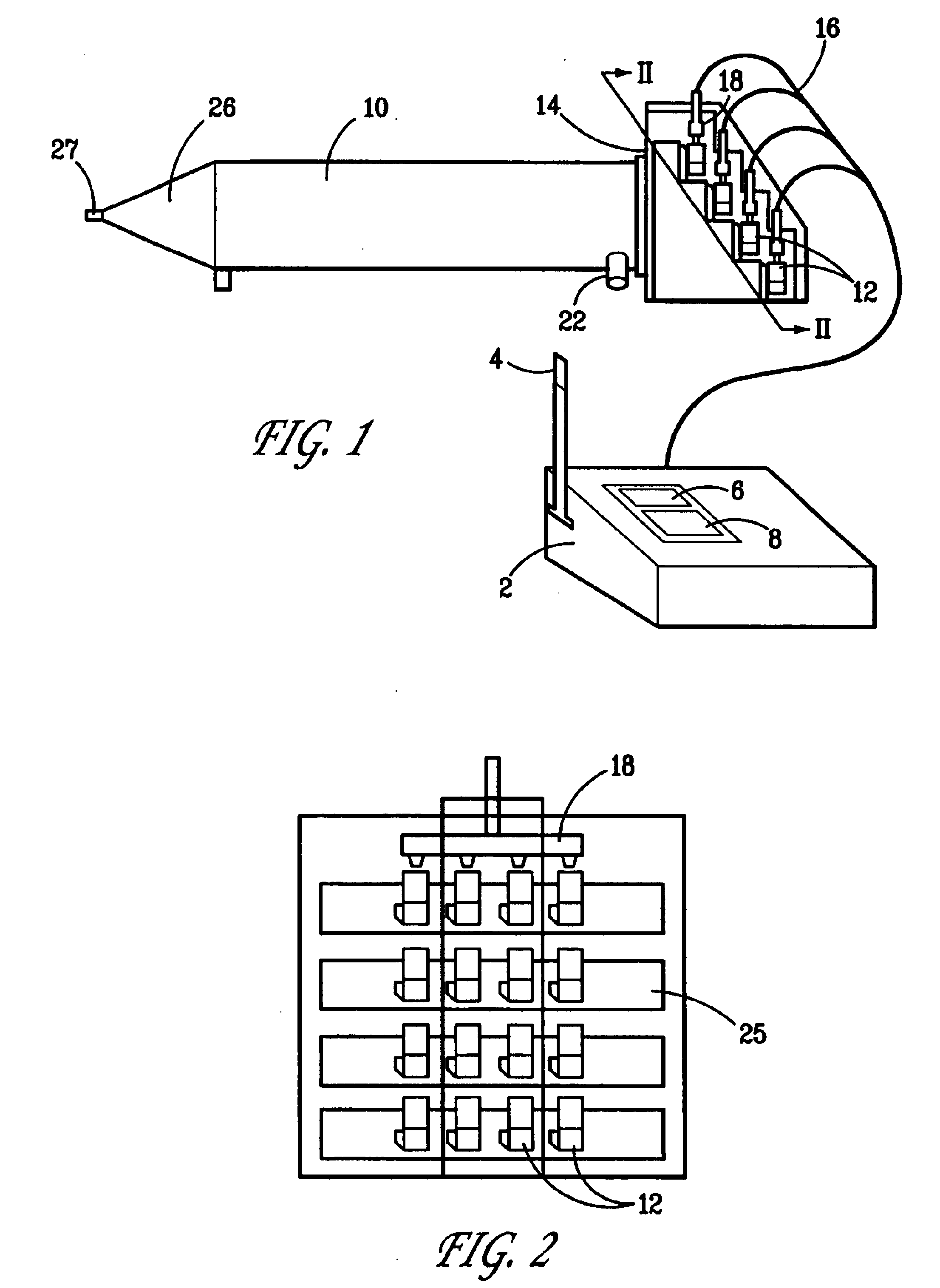
One preferred apparatus according to the invention is shown in FIGS. 1 and 2. Control unit 2, consisting of a status indicator 4, display 6, and keypad 8, controls the flow of drug product into the plenum mixer generator chamber 10 by means of individual pulsatile delivery devices 12 having actuator means in the form of plunger bars 18 and compressed air lines and associated wiring 16. The devices (MDIs) are shown positioned on end-plate 14 in a stepped arrangement within cassettes 25 to maximize placement density. The delivered aerosol exits chamber 10 through exit tube 27, as shown.
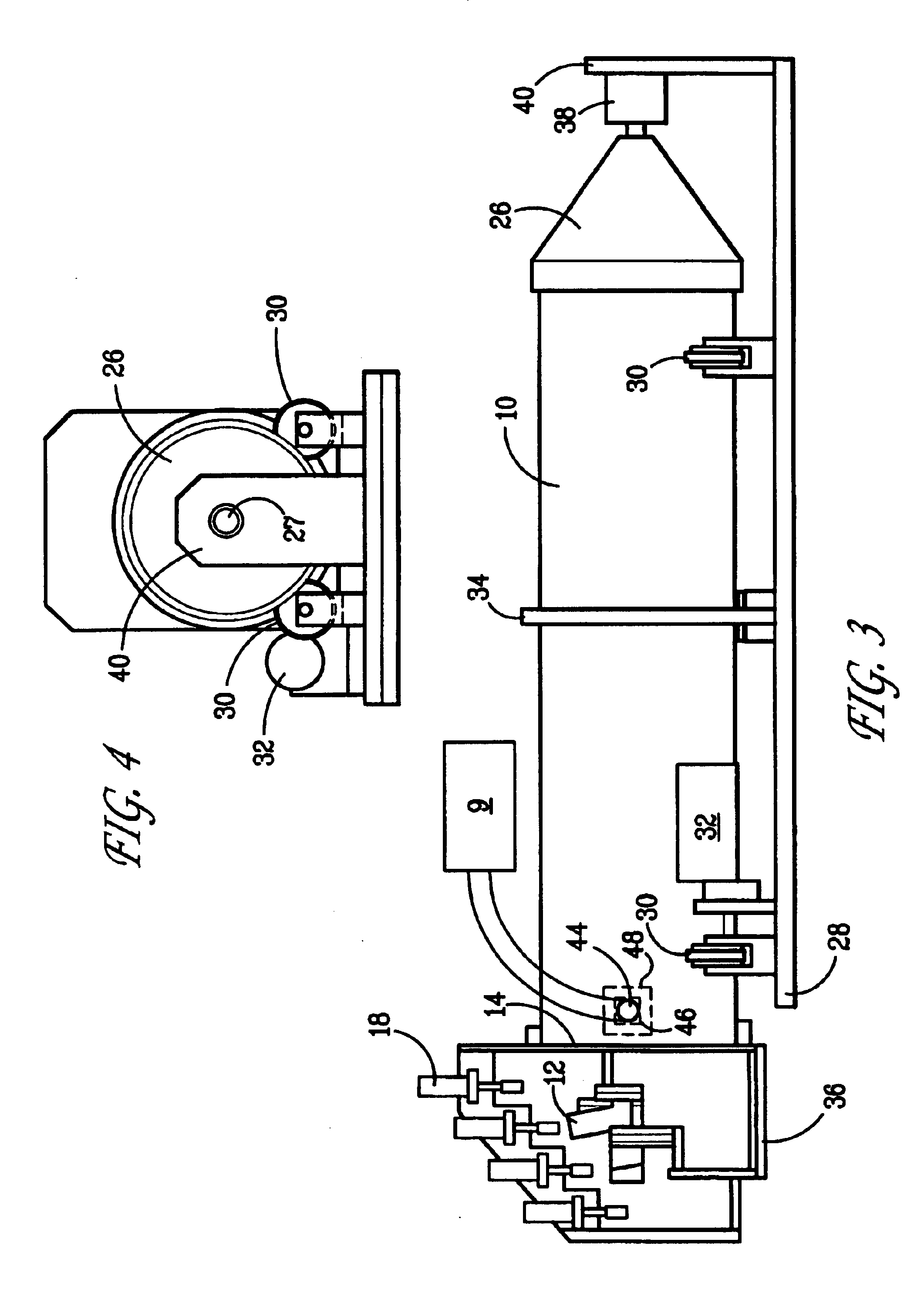
Such an apparatus preferably provides an unobstructed path from the MDI heads in the generator / diluter of at least 18 inches. This distance is sufficient both to allow evaporation of the propellant from the primary particles emitted by the MDI, and to avoid loss of test article by impaction of the primary particles, which are ejected from the MDI at speeds as great as 50 meters per second. The MDI plumes and the dilution air in this design both flow along the horizontal axis. The pulsatile flow is dampened (to 20% or less) by controlling the residence time in the mixing / dilution stage so that residence time exceeds the time between MDI bursts by at least five fold to ensure non-pulsatile aerosol delivery and to allow for evaporation of solvent.
To generate the concentration of aerosol required, up to sixteen MDI's are mounted in banks of four on stepped end plate 14. Each bank of four is activated by means of a pneumatic drive actuator. The pneumatic drives are controlled by a microprocessor, which fires the banks of MDIs sequentially. Each bank is activated up to six times a minute to achieve the concentration required. To minimize pulsatile aerosol generation, different banks of MDIs are fired at least every 90 seconds. Chamber 10 into which the MDIs fire preferably is three feet long to minimize plume impaction. The most frequent cause of system failure is jamming of an MDI valve. For this reason each set of four MDIs is mounted in a replaceable cassette. This design facilitates replacement of sets of MDIs when they are exhausted, or when an MDI fails.
Chamber 10 ends in a conical reducing adapter 26 of a 45 degree angle. One inch brass tubing can be used to lead to the brass inlet nozzle of the anodized aluminum nose-only flow-past exposure chamber, such as those available from Intox, Albuquerque, N.Mex. (not shown). The exposure chamber design ensures that rebreathing, with consequent variability in animal exposure, is minimized. The nose-only exposure tubes typically are made of polycarbonate, with anodized aluminum nose-cones, and Cannon butt-plates. The exposure tube design is a marked improvement over other commercial designs, as it enables animals to exit from the front of the tube at exposure termination, reducing stress on the animals and excessive animal handling.

Problems solved by technology

When a new pharmaceutical is being produced in the laboratory, it remains very expensive, even if scale-up following satisfactory toxicity testing is expected to reduce the ultimate price to consumers.
Current MDI aerosol generators, however, are rather inefficient in aerosol delivery.
Thus, problems are encountered due to particle loss by impaction unless an adequate trajectory is allowed.
A further problem is that an MDI produces a sudden burst of aerosol, or pulsatile flow, whereas the nose-only exposure chambers which meet GLP and FDA regulations must have a steady or uniform aerosol concentration delivered to them.

Method used


Image

  • Apparatus for delivering air-borne substances
  • Apparatus for delivering air-borne substances
  • Apparatus for delivering air-borne substances

Examples


example 2

Particle size distribution was measured using an INTOX eight-stage cascade impactor. Samples were taken during a prestudy testing period to determine particle size distribution. Size distributions were reported in terms of the Geometric Standard Deviation (GSD (.sigma..sub.g)) and the Mass Median Aerodynamic Diameter (MMAD, in .mu.m), as determined by the cascade impactor. This analysis was based on an algorithm describing test article aerosols which are distributed normally with respect to the logarithm of aerodynamic equivalent diameter (the diameter of a unit density sphere with the same settling velocity as the particle). Gravimetric and HPLC analyses of cascade impactor filters were both performed, but the results based on the HPLC analysis of test article on the filters data were considered the definitive measure of particle size.

Results are shown in FIG. 6.


PUM


Abstract

Apparatus and methods for delivery of air-borne materials from pulsatile delivery devices by passing the emissions from such devices and air in a coaxial manner through a suitable mixing chamber. Preferred apparatus include a chamber defining an axis of air flow, a plurality of pulsatile delivery devices, an actuator in communication with the devices for selective actuation thereof, and a device for introducing air at a first end of the chamber and for flowing that air substantially along the axis. The pulsatile delivery devices are positioned at the first end of the chamber such that actuation of the devices emits an air-borne substance substantially along the axis of air flow.

Description

The present invention is directed to apparatus for delivering air-borne substances and, more particularly, to apparatus which deliver such substances from pulsatile devices yet do so in a uniform (i.e., non-pulsatile) manner.Metered dose inhalers ("MDIs") have been the preferred method of delivery of drugs for treatment of asthma and other diseases of the respiratory tract for over twenty years. Human beings open their mouths voluntarily to inhale a therapeutic bolus, while animal models used in inhalation toxicology must be tested using continuous flow systems. FDA requirements and good laboratory practices (GLP) specify that a uniform concentration of the drug be maintained, although the output from conventional MDIs is pulsatile. Additionally, the Montreal Convention requires that existing MDI formulations be replaced by more environmentally benign formulations, using new propellant mixtures to replace chlorofluoro hydrocarbons. FDA regulations also require that each new formulat...

Claims


Application Information

Patent Timeline
IPC IPC(8): A61M15/00
CPCA61M15/0086
Inventor ROTHENBERG, SIMON J.YEH, HSU CHIGREENSPAN, BERNARD J.
Owner CHARLES RIVER LAB INC
Learn More