Biosensor

a biosensor and sensor technology, applied in the field of biosensors, can solve the problems of longer measurement time, increase the amount of electron mediators supplied, increase the accuracy of measurement, and increase the response.

Inactive Publication Date: 2004-05-25
PANASONIC HEALTHCARE HLDG CO LTD
View PDF14 Cites 247 Cited by
  • Summary
  • Abstract
  • Description
  • Claims
  • Application Information

AI Technical Summary

Benefits of technology

FIG. 2 is a longitudinal cross-sectional view of the biosensor in accordance with the present invention. A reagent system 7 containing an enzyme and an electron mediator is formed on the base plate 1 on which the electrode system is formed. The reagent system 7 is formed over the electrode system so as to come in contact with the working electrode 4 or the counter electrode 5. This substantially increases the amount of the electron mediator supplied to electrochemical reactions at the electrodes, so that it is possible to obtain a larger response. The reagent system 7, in the example as shown in the figure, is composed of a hydrophilic polymer layer 7a and a layer 7b that is formed thereon and contains GOD, GLN and the electron mediator potassium ferricyanide.
When a sample solution is brought into contact with the open end of the slit 10 forming the sample solution supply pathway of the sensor with the structure as shown in FIG. 2, the sample solution is introduced into the sample solution supply pathway because of capillary phenomenon, thereby to dissolve the reagent system 7, so that the enzyme reaction proceeds. In this way, when the sample solution supply pathway is formed by integrating a cover member composed of the spacer 8 and the cover 9 to the base plate 1 on which the electrode system is provided, the amount of the sample solution containing the substrate to be measured supplied to the sensor can be made constant, so that it is possible to raise the accuracy of the measurement.

Problems solved by technology

Particularly, trying to obtain a sufficient sensitivity to high concentrations of glucose while securing a good accuracy requires an increase in reaction time in order to generate a large amount of the reductant of electron mediator, so that the measurement tends to require longer time.

Method used


Image

  • Biosensor
  • Biosensor
  • Biosensor

Examples


example 2

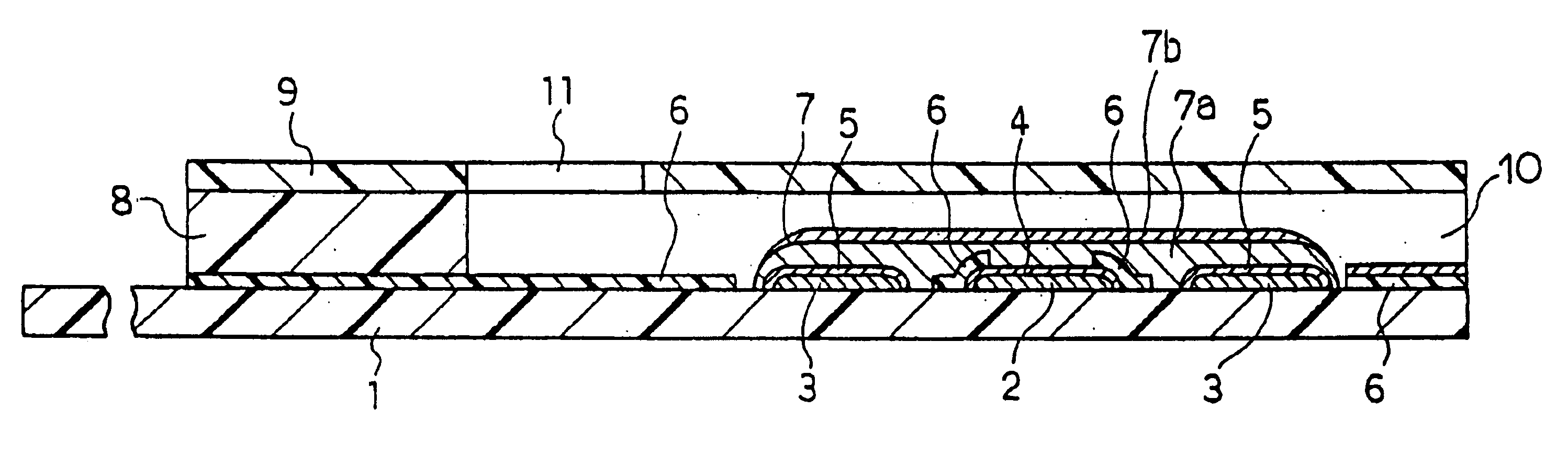
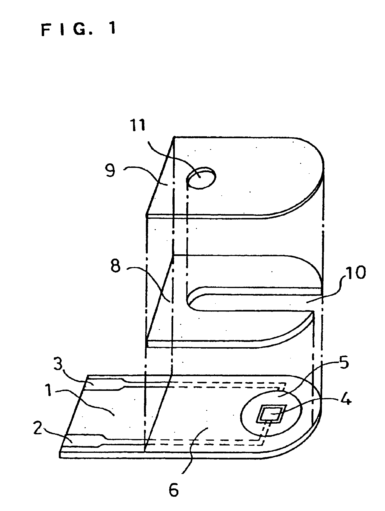
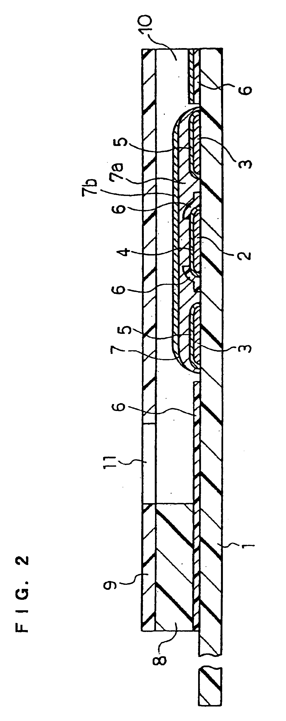
In the same manner as in Example 1, the CMC layer 7a and the layer 7b containing GOD, GLN and potassium ferricyanide were formed over the electrode system on the base plate 1. This example does not use the spacer 8 and the cover 9.

Over the reagent system 7 of the sensor was dropped an aqueous solution containing a certain amount of D-glucose. The amount of the D-glucose aqueous solution dropped was made a predetermined amount. After a lapse of predetermined time, a voltage of 500 mV was applied to the working electrode 4 with respect to the counter electrode 5, and the current value flowing at this time was measured. Between the response current obtained and the D-glucose concentration, a favorable linear relationship was observed. Also, the response current obtained was significantly larger than the response current obtained from the sensor not containing GLN in the reagent system 7. In this way, it was found that, even when the sensor did not have the cover member, the above-descr...

example 3

In this example, a sensor was produced in the same manner as in Example 1, except that a pH buffer composed of a combination of dipotassium hydrogenphosphate (K.sub.2 HPO.sub.4) and potassium dihydrogenphosphate (KH.sub.2 PO.sub.4) was added to the layer 7b such that the pH realized by water introduction became 7.

An aqueous solution containing a certain amount of D-glucose was supplied to the opening of the sample solution supply pathway, and after a lapse of predetermined time, a voltage of 500 mV was applied to the working electrode 4 with respect to the counter electrode 5 and the current value flowing at this time was measured. The response current obtained was higher than that of the sensor of the Example 1 not containing a pH buffer in the reagent system 7. This result was obtained presumably because, due to the addition of the pH buffer, the pH of the sample solution was maintained at a value at which GLN more effectively decomposed D-glucono-.delta.-lactone. It is considered...

example 4

In this example, a sensor was produced in the same manner as in Example 1, except that PQQ dependent glucose dehydrogenase (hereinafter referred to as PQQ-GDH) was used in place of the enzyme GOD of the layer 7b. The ratio of the activity unit number of GLN to PQQ-GDH was GLN:PQQ-GDH=2:1. The amount of PQQ-GDH used was 2 units.

An aqueous solution containing a certain amount of D-glucose was supplied to the opening of the sample solution supply pathway of the sensor, and after a lapse of predetermined time, a voltage of 500 mV was applied to the working electrode 4 with respect to the counter electrode 5 and the current value flowing at this time was measured. The response current obtained exhibited a favorable linear relationship with respect to the concentration of D-glucose. Also, for comparison, a sensor not containing GLN in the reagent system 7 was produced and the response value was measured in the same manner as above. In each glucose concentration, the response of the sensor...


PUM

PropertyMeasurementUnit
voltageaaaaaaaaaa
concentrationsaaaaaaaaaa

Abstract

A biosensor comprising an electrically insulating base plate, an electrode system containing a working electrode and a counter electrode disposed on the base plate, and a reagent system comprising at least an oxidoreductase, a hydrophilic polymer and an electron mediator, wherein the reagent system further comprises a substance having a function to convert an organic product generated by direct reaction of a substrate to be measured with the oxidoreductase to another compound.

Description

The present invention relates to a biosensor for facilitating rapid and highly accurate quantification of a substrate such as glucose contained in a sample.With the aim of realizing simple quantification of body fluid components by ordinary people, various types of biosensors have recently been developed which utilize a specific catalytic action of enzymes.In the following, a method of glucose quantification will be explained as an example of the method of quantifying a component contained in a sample solution. As an electrochemical method of glucose quantification, a method using a combination of glucose oxidase (hereinafter abbreviated to GOD) with an oxygen electrode or a hydrogen peroxide electrode is generally well-known.GOD selectively oxidizes .beta.-D-glucose as a substrate to D-glucono-.delta.-lactone using oxygen as an electron mediator. In the presence of oxygen, oxygen is reduced to hydrogen peroxide during the oxidation reaction process by GOD. The decreased volume of o...

Claims


Application Information

Patent Timeline
Patent Type & Authority Patents(United States)
IPC IPC(8): C12Q1/00G01N33/487
CPCC12Q1/005
Inventor NAKAMINAMI, TAKAHIROWATANABE, MOTOKAZUIKEDA, SHINNANKAI, SHIRO
Owner PANASONIC HEALTHCARE HLDG CO LTD
Why Eureka
Try Eureka