Hot-wire type air flow meter for internal combustion engine

a technology of air flow meter and internal combustion engine, which is applied in the direction of fluid speed measurement using thermal variables, electric control, instruments, etc., can solve the problems of exothermic portion, excessive current flow, and time-consuming water drop evaporation, so as to prevent the deterioration of the resistor

Inactive Publication Date: 2004-06-22
HITACHI LTD
View PDF6 Cites 28 Cited by
  • Summary
  • Abstract
  • Description
  • Claims
  • Application Information

AI Technical Summary

Benefits of technology

According to an aspect of the invention, there are provided: means for detecting a heating state of an exothermic resistor by distinguishing a case where a waterdrop, an oil droplet, or the like is deposited onto the exothermic resistor portion from a normal case where there is no deposition; and circuit means for limiting a heating time by the detected heating state. Thus, only in the case where the waterdrop, oil droplet, or the like is deposited onto the exothermic resistor portion, the heating state is limited without narrowing a measuring range of an inherent flow rate and a deterioration of the resistor can be prevented.

Problems solved by technology

Such a system is used, particularly, for measurement of a flow rate of the compressed air and there is a problem that although a waterdrop is instantaneously evaporated usually at 100.degree. C. at an atmospheric pressure, in the compressed air, an evaporation temperature of the water is high, it takes time to evaporate the waterdrop, and an excessive current flows in an exothermic portion.
In an internal combustion engine such as an ordinary gasoline engine or the like, therefore, since a power source voltage is usually small to be about 12V, an operating current to the exothermic resistor is limited and it takes time to heat, so that it is difficult to accurately measure an air flow rate for a predetermined time at the start of an engine of an automobile or the like.
In a hot-wire air flow meter, however, the maximum flow rate which can be measured is limited unconditionally to a certain degree by the heat capacity and a heating temperature of the exothermic resistor which is used for measurement and by a power source voltage which can be applied.
It is because when the heat capacity is small, if it is intended to raise a measuring sensitivity (maximum flow rate) of the flow rate by increasing the heating temperature, a limitation such that the exothermic resistor deteriorates when the heating temperature is equal to or higher than a predetermined value occurs.
Even in case of the applied voltage which does not cause a problem in the ordinary operation, therefore, if the temperature elevation continues, there is a possibility that the resistor of a small heat capacity constructed by the thin film is deteriorated by the heat and, in the worst case, the diaphragm is broken by a thermal stress.
Although the excessive temperature elevation can be prevented by limiting the voltage applied to the hot-wire type resistor so as not to locally raise the heating temperature of the exothermic resistor, there is a problem that a measuring range of the inherent flow rate is also narrowed.

Method used


Image

  • Hot-wire type air flow meter for internal combustion engine
  • Hot-wire type air flow meter for internal combustion engine
  • Hot-wire type air flow meter for internal combustion engine

Examples


first embodiment

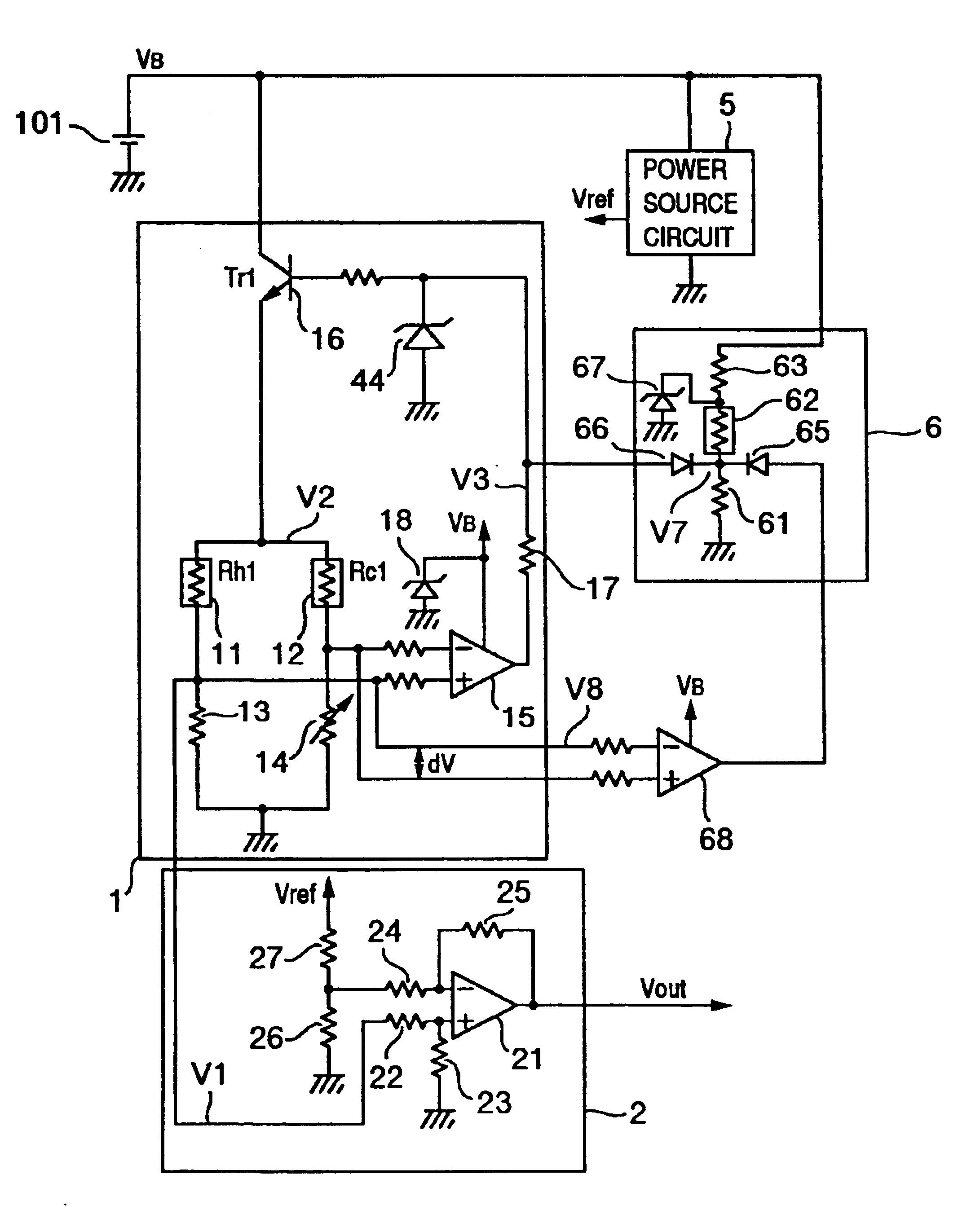
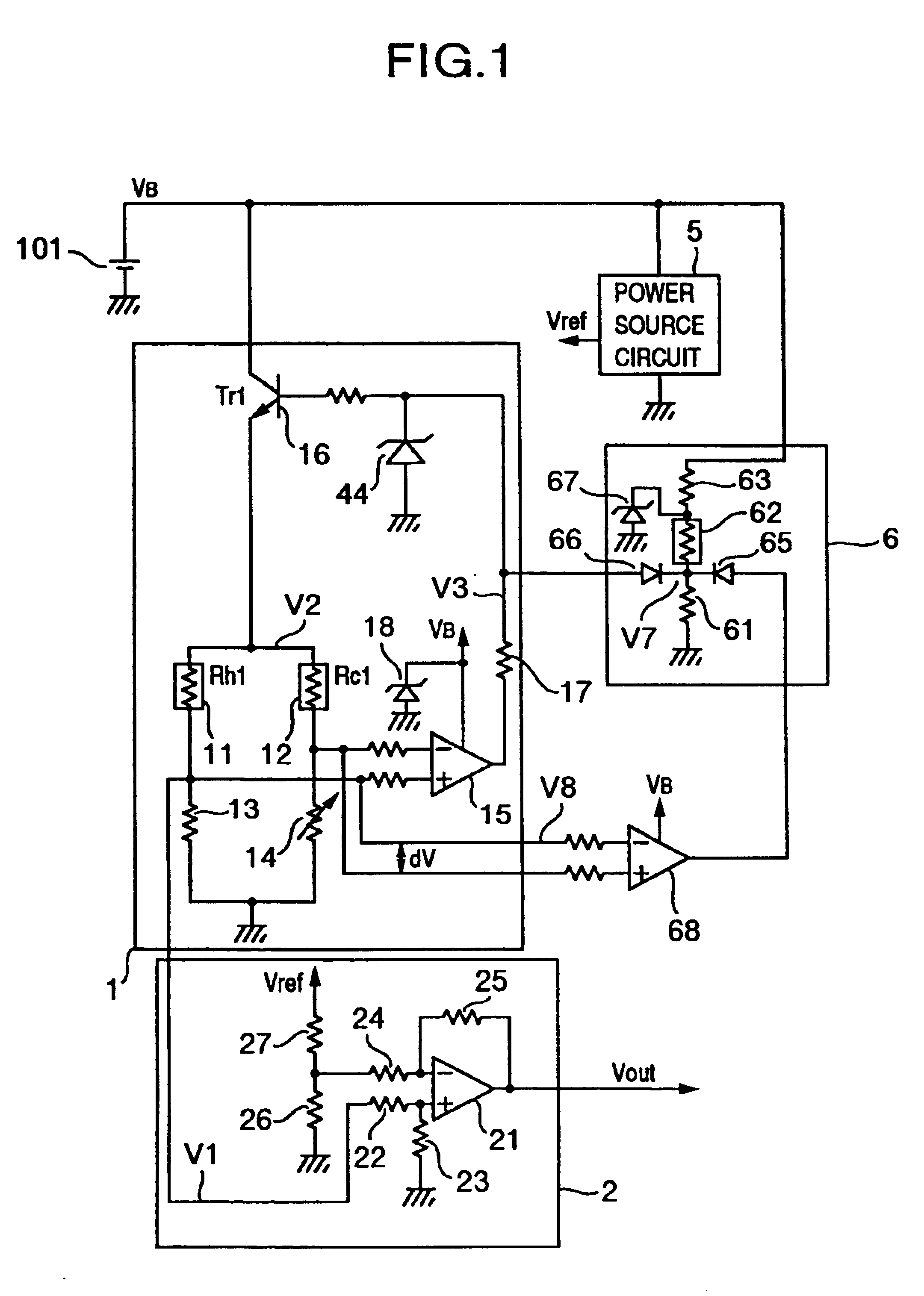
An example of a construction of a hot-wire type air flow meter according to the invention will be described hereinbelow with reference to FIG. 1. A hot wire driving circuit I is connected to a power source 101 and generates a signal corresponding to an air flow rate. A hoisten-bridge circuit is constructed by: an exothermic resistor 11; a temperature compensation resistor (a resistor for measuring a suction air temperature, a temperature detecting element of a fluid, a temperature sensor of an air and a medium, a fluid temperature sensing unit, a temperature dependent resistor) 12 as a resistor whose resistance value varies in accordance with an ambient air temperature; and resistors 13 and 14. The hot wire driving circuit 1 is constructed in such a manner that a current flowing in the exothermic resistor 11 is adjusted by a differential amplifier 15 and a transistor 16 so that a potential difference at a middle point of a bridge is equal to zero by the hoisten-bridge circuit. When ...

second embodiment

FIG. 9 shows the second embodiment in case of using such a resistor pattern. The hot wire driving circuit 1 is constructed in such a manner that a current flowing in the exothermic resistor 211a is adjusted by the differential amplifier 15 and transistor 16 so that the potential difference at the middle point of the bridge is equal to zero by a hoisten-bridge circuit constructed by the exothermic resistor 211a, temperature compensation resistor 211c, and resistors 13 and 14.

The resistors 211d, 211e, 211f, and 211g for detecting a temperature construct a bridge circuit by applying a voltage Vcc to a power source circuit 5. As a voltage which is applied to the bridge circuit, it is also possible to form a ratio metric construction using an external voltage. This differential voltage is amplified by a differential amplifier 2131 and resistors 2132, 2133, 2134, and 2137 around a virtual zero point voltage V of, as a center, obtained by dividing a reference voltage Vref by resistors 2135...

third embodiment

the invention will now be described with reference to FIG. 14. A hoisten-bridge circuit based on the constant voltage Vcc driving is constructed by: the exothermic resistor 11; a heating portion of the current detecting resistor 13; a temperature detecting resistor (heating temperature sensor) 111 arranged on the side of the exothermic resistor 11 so as to be mounted on the same substrate as that of the exothermic resistor 11; the temperature compensation resistor 12; and the resistors 13 and 14. The hot wire driving circuit 1 is constructed in such a manner that a current flowing in the exothermic resistor 11 is adjusted by the differential amplifier 15 and transistor 16 so that the potential difference at the middle point of the bridge is equal to zero by the hoisten-bridge circuit. When the heating temperature of the exothermic resistor 11 is low, the output of the differential amplifier 15 increases and the apparatus operates so as to heat more. With this construction, the resis...


PUM


Abstract

A hot-wire type air flow meter for an internal combustion engine has an exothermic resistor film provided on a thin portion formed on a silicon substrate and a control circuit for controlling a voltage to be applied to the resistor film or a current to be supplied. The resistor film is arranged in a suction pipe of the internal combustion engine and heat is emitted to an air through the resistor film. In the case where a liquid droplet is deposited onto the resistor film, the control circuit controls the applied voltage to a value smaller than a voltage which is applied to the resistor film at the time of measuring a maximum specified measuring range or controls the supply current to a value smaller than a current flowing in the resistor film at the time of measuring the maximum specified measuring range.

Description

1. Field of the InventionThe invention relates to a measuring apparatus of an air flow rate and, more particularly, to a hot-wire type air flow meter (heat flow meter) suitable for detection of a suction air flow rate of an internal combustion engine.2. Description of Related ArtHitherto, as an air flow rate measuring apparatus which is provided for an electronic control type fuel injection apparatus of an internal combustion engine such as an automobile or the like and measures a suction air flow rate, a number of hot-wire type apparatuses have been used because a mass air flow rate can be directly detected. In this instance, to assure a reliability of an exothermic resistor, a sensor having a certain extent of heat capacity which is constructed by winding a platinum wire around a bobbin and coating it with glass, forming a thin film resistor onto a ceramic substrate, or the like is often used. In a sensor having a large heat capacity, although a system such that a current is limit...

Claims


Application Information

Patent Timeline
Patent Type & Authority Patents(United States)
IPC IPC(8): G01F1/684G01F1/698G01F1/696G01P5/12F02D45/00G01F1/68G01F1/692G01F1/699
CPCG01F1/6845G01F1/696G01F1/698
Inventor KANKE, ATSUSHIYAMADA, MASAMICHINAKADA, KEIICHIWATANABE, IZUMISONOBE, HISAO
Owner HITACHI LTD
Why Eureka
Try Eureka