Flared coronary artery bypass grafts

a technology of bypass grafts and coronary arteries, which is applied in the field ofvascular grafts, can solve the problems of reducing the radial compliance or longitudinal compliance of an artificial graft, affecting the radial compliance or longitudinal compliance of the artificial graft, and the internal diameter of the vascular graft less than about six (6) mm,

Inactive Publication Date: 2004-11-23
THORATEC CORPORTION
View PDF49 Cites 86 Cited by
  • Summary
  • Abstract
  • Description
  • Claims
  • Application Information

AI Technical Summary

Problems solved by technology

Known grafts, however, may kink or collapse mechanically under a variety of circumstances, such as when the graft is bent during the contraction of the surrounding muscle or tissue, or when external pressure is applied to the graft when the graft recipient moves.
In addition, small diameter vascular grafts, i.e., internal diameters less than about six (6) mm, have a tendency to become obstructed due to neoint

Method used


Image

  • Flared coronary artery bypass grafts
  • Flared coronary artery bypass grafts
  • Flared coronary artery bypass grafts

Examples


Embodiment Construction

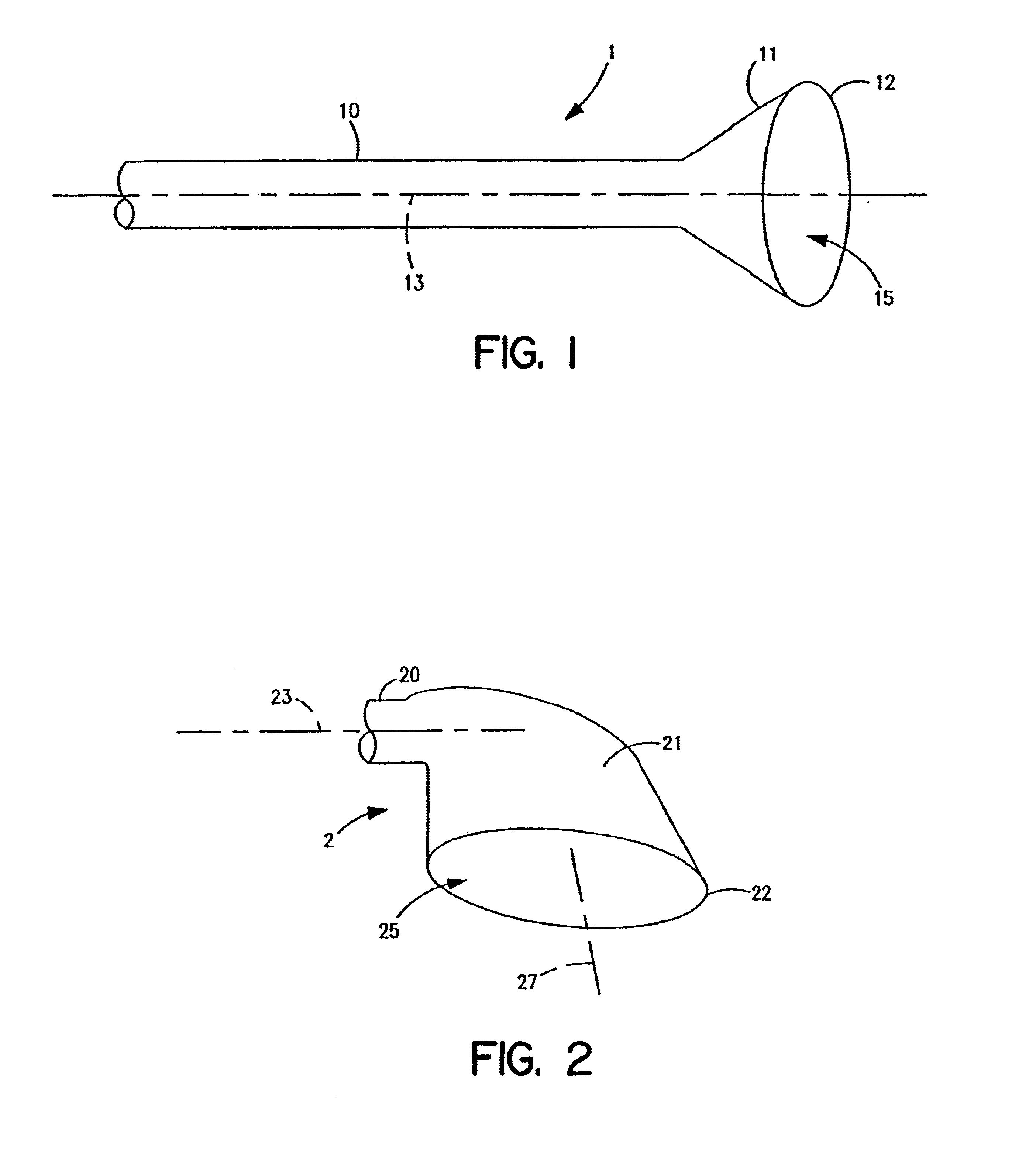
FIG. 1 depicts a graft 1 according to the invention, namely a CABG, having a flared end. A tubular portion 10 of graft 1 has one flared end, formed by a skirt 11, which is symmetrically flared to form a substantially circular opening 12. The axis of opening 12 is substantially parallel to, if not concentric with, an axis 13 of the tubular portion 10. Thus, opening 12 may be substantially concentric with tubular portion 10. Skirt 11 forms an open space 15, which is circumferentially and volumetrically larger than the space provided in a corresponding section of the tubular portion 10. Preferably, graft 1 is monolithic, i.e., it is formed without intervening seams or overlap, whereby skirt 11 forms a continuous, integral, monolithic section of graft 1.

FIG. 2 depicts another embodiment of a graft 2 having a flared end according to the invention showing only the flared end, which is modified compared to that shown in FIG. 1. A tubular portion 20 of graft 2 has one flared end, formed by ...


PUM


Abstract

A bypass graft includes a tubular portion having an internal tubular diameter and a first end and a second end. The tubular portion has a central axis. A flared portion has an adjoining end, wherein the adjoining end of the flared portion is integrally formed on and is substantially concentric with the second end of the tubular portion, and a flared end, wherein the flared end has a flared end internal diameter, such that the internal flared end diameter is greater than the internal tubular diameter. The flared portion includes a circumferential skirt for surgical attachment of the graft to a patient's blood vessel. A method for manufacturing a bypass graft, includes the steps of providing a mandrel having a tubular portion and a flared end with a flared end central axis; forming a layer of polyurethane over the mandrel; drying the layer of polyurethane on the mandrel; forming a skirt edge around the flared end of the mandrel to form an opening at a predetermined angle to the flared end central axis; forming a second edge around the tubular portion of the mandrel, and removing the graft from the mandrel.

Description

1. Field of the InventionThe present invention relates generally to vascular grafts having at least one flared end to facilitate anastomosis to a blood vessel, such as a vein or an artery, or between blood vessels. More particularly, the present invention relates to polymer grafts having at least one flared end, which forms a skirt or cuff to form an anastomosis with the aorta.2. Description of Related ArtWhen a blood vessel becomes occluded, a vascular surgeon may restore proper blood flow by performing a surgical bypass procedure. In the medical treatment of patients with diseased arteries or veins, surgeons may replace or bypass the occluded vessel with prosthetic conduits, such as vascular grafts. Examples of such grafts have been made from a polyester fabric (e.g., Dacron.RTM. fabric), or polytetrofluroethylene (PTFE) fabric (e.g., Teflon.RTM. fabric). Fabrics woven or knitted of these polymers also have been used as patches or reinforcements. Known procedures for restoring pro...

Claims


Application Information

Patent Timeline
IPC IPC(8): A61F2/06A61L27/00A61L27/50A61L27/40
CPCA61F2/06A61L27/40A61L27/507C08L75/00
Inventor FARRAR, DAVID J.
Owner THORATEC CORPORTION
Why Eureka
Try Eureka