Hard film for cutting tools, cutting tool coated with hard film, process for forming hard film, and target used to form hard film

a technology of hard film and cutting tool, applied in the field of hard film for cutting tool, cutting tool coated with hard film, process for forming hard film, target used to form hard film, can solve the problems of limited improvement in wear resistance, high hardness and good oxidation resistance of conventional tialn film, etc., and achieves poor sinterability, low relative density, and high hardness

Inactive Publication Date: 2004-11-30
KOBE STEEL LTD
View PDF46 Cites 168 Cited by
  • Summary
  • Abstract
  • Description
  • Claims
  • Application Information

AI Technical Summary

Benefits of technology

The present invention was completed in view of the foregoing. It is an object of the present invention to provide a hard film for cutting tools which is superior in wear resistance to TiAlN film and permits high-speed efficient cutting, a process for forming said hard film, and a target used to efficiently form a hard film for cutting tools by said process.
Although it is possible to produce a target from the mixed powder by hot pressing (HP), the resulting target does not have a sufficiently high relative density because Cr is a high-melting metal. Instead of producing a target from a mixed powder as mentioned above, it is also possible to produce a target from a previously alloyed powder, by means of CIP or HIP, or through melting and solidifying. The CIP or HIP with an alloy powder offers the advantage that the resulting target has a uniform composition; however, it also suffers the disadvantage that the resulting target tends to have a low relative density because the alloy powder is poor in sinterability. The method involving the melting and solidifying of an alloyed powder offers the advantage that the resulting target has a comparatively uniform composition but has the disadvantage that the resulting target is subject to cracking and shrinkage cavity at the time of solidification. It does not easily yield the target of the present invention.

Problems solved by technology

In other words, the conventional TiAlN film cannot have both high hardness and good oxidation resistance because there is a limit to increasing hardness by increasing the compositional ratio of Al.
Consequently, it is limited also in improvement in wear resistance.

Method used


Image

  • Hard film for cutting tools, cutting tool coated with hard film, process for forming hard film, and target used to form hard film
  • Hard film for cutting tools, cutting tool coated with hard film, process for forming hard film, and target used to form hard film
  • Hard film for cutting tools, cutting tool coated with hard film, process for forming hard film, and target used to form hard film

Examples


example 1

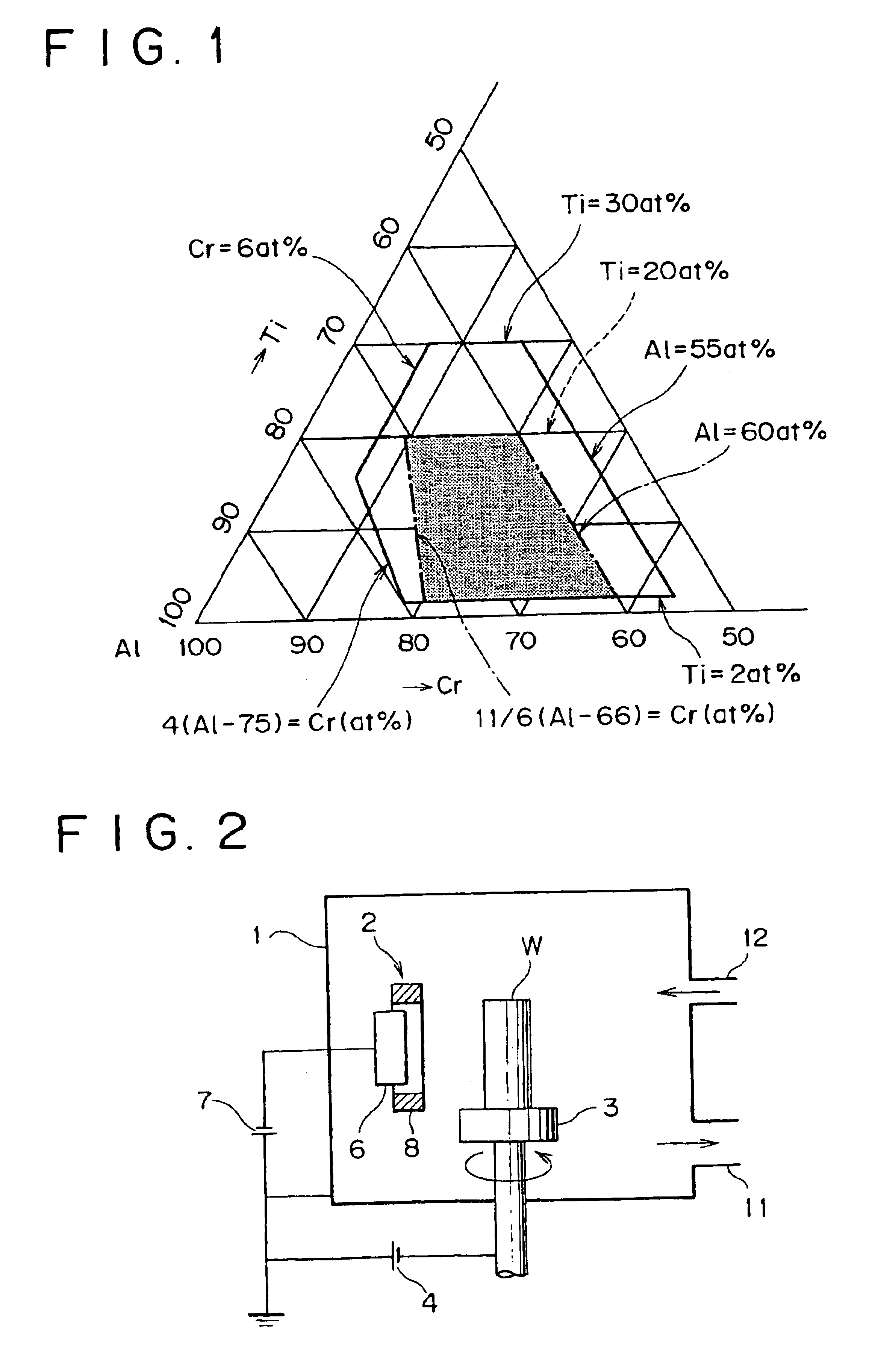
A target of alloy composed of Ti, Cr, and Al was mounted on the cathode of the AIP apparatus shown in FIG. 2. A substrate was mounted on the holder. The substrate is a chip of cemented carbide, a square end mill of cemented carbide (10 mm in diameter, with two edges), or a piece of platinum foil (0.1 mm thick). The chamber was evacuated to a degree of vacuum lower than 3.times.10.sup.-3 Pa while the substrate was being heated to 400.degree. C. by means of a heater placed in the chamber. The substrate was given a bias voltage of 700V in an argon atmosphere at 0.66 Pa, so that the substrate was cleaned with argon ions for 10 minutes. Subsequently, nitrogen gas was introduced into the chamber. With the chamber pressure kept at 2.66 Pa, an arc current of 100A was applied for film forming. A 4-.mu.m thick film was formed on the surface of the substrate. Incidentally, a bias voltage of 150V was applied to the substrate so that the substrate was kept negative with respect to earth potentia...

example 2

Samples Nos. 1, 4, 7, 11, 16, 18, 19, 22, 24, and 27 in Example 1, which are end mills coated with the hard film, were tested for wear resistance by cutting several works of quenched JIS-SKD61 (HRC50) under the following conditions.

Cutting speed: 200 m / min

Feed speed: 0.07 mm / edge

Depth of cut: 5 mm

Pick feed: 1 mm

Cutting oil: air blow only

Cutting direction: down cutting

After cutting over a length of 20 meters, the cutting edge of the end mill was examined under an optical microscope to measure the worn width. The results are shown in Table 2.

It is noted from Table 2 that the samples of end mills Nos. 1, 4, 7, 11 and 16, which are coated with the film meeting the requirements of the present invention, are superior in wear resistance (in terms of worn width) to the samples Nos. 18, 19, 22, 24, and 27, which are coated with the film not meeting the requirements of the present invention.

example 3

A target of alloy composed of Ti, Cr, Al, and Si was mounted on the cathode of the AIP apparatus shown in FIG. 2. A substrate was mounted on the holder. The substrate is a chip of cemented carbide, a square end mill of cemented carbide (10 mm in diameter, with four edges), or a piece of platinum foil (0.2 mm thick). The chamber was evacuated to a degree of vacuum lower than 3.times.10.sup.-3 Pa while the substrate was being heated to 550.degree. C. by means of a heater placed in the chamber. The substrate was cleaned with argon ions for 10 minutes. Subsequently, nitrogen gas or a mixture gas of nitrogen and methane was introduced into the chamber. With the chamber pressure kept at 2.66 Pa, an arc current of 100A was applied for film forming. An approximately 3-.mu.m thick film was formed on the surface of the substrate. Incidentally, a bias voltage of 100-200V was applied to the substrate so that the substrate was kept negative with respect to earth potential during film forming.

Aft...


PUM

PropertyMeasurementUnit
bias voltageaaaaaaaaaa
temperatureaaaaaaaaaa
total pressureaaaaaaaaaa

Abstract

A hard film for cutting tools which is composed of(where a, b, c, and d denote respectively the atomic ratios Al, Cr, Si, and B, and e denotes the atomic ratio of N.)

Description

1. Field of the InventionThe present invention relates to a hard film to improve the wear resistance of cutting tools such as tips, drills, and end mills, a cutting tool coated with said hard film which exhibits excellent wear resistance, a process for forming said hard film, and a target used as a vapor source to form said hard film.2. Description of the Related ArtsIt has been common practice to coat cutting tools made of cemented carbide, cermet, or high speed tool steel with hard film of TiN, TiCN, TiAlN, or the like for the purpose of improving their wear resistance.Because of its excellent wear resistance as disclosed in Japanese Patent No. 2644710, the film of compound nitride of Ti and Al (referred to as TiAlN hereinafter) has superseded the film of titanium nitride, titanium carbide, or titanium carbonitride to be applied to cutting tools for high speed cutting or for high hardness materials such as quenched steel.There is an increasing demand for hard film with improved we...

Claims


Application Information

Patent Timeline
Patent Type & Authority Patents(United States)
IPC IPC(8): C23C14/06C23C14/34C23C30/00C22C14/00C22C29/04C22C29/14C22C29/16C22C29/18C23C4/10
CPCC23C14/0641C23C14/0664C23C30/005C23C14/3414Y10T428/12785Y10S264/91C23C14/06
Inventor YAMAMOTO, KENJISATOU, TOSHIKIMORIKAWA, YASUOMIHANAGURI, KOJITAKAHARA, KAZUKI
Owner KOBE STEEL LTD
Why Eureka
Try Eureka