MEMS digital-to-acoustic transducer with error cancellation

Inactive Publication Date: 2004-12-07
CARNEGIE MELLON UNIV
View PDF15 Cites 123 Cited by
  • Summary
  • Abstract
  • Description
  • Claims
  • Application Information

AI Technical Summary

Benefits of technology

The present invention represents a substantial advance over relevant art electroacoustic transducers. The present invention has the advantage that it can be manufactured at a lower cost of production in comparison to relevant art acoustic transducers. The acoustic transducer according to the present invention converts a digital audio input signal directly into a sound wave. The present invention also has the advantage that the size of the acoustic transducer can be significantly reduced in comparison to relevant art audio transducers by integrating the electroacoustic transducer onto a substrate using microelectromechanical systems (MEMS) tec

Problems solved by technology

Thus, there is little cost benefit in manufacturing such audio transducers in high volume quantities.
In addition, the performance of relevant art electroacoustic transducers is limited by the fluctuations in the performance of the discrete constituent components due to, for example, changes in the ambient temperature, as well as by variations in the assembly process.
The discrete nature of the voice coil exposes it to the consistency, cost and qual

Method used


Image

  • MEMS digital-to-acoustic transducer with error cancellation
  • MEMS digital-to-acoustic transducer with error cancellation
  • MEMS digital-to-acoustic transducer with error cancellation

Examples


Embodiment Construction

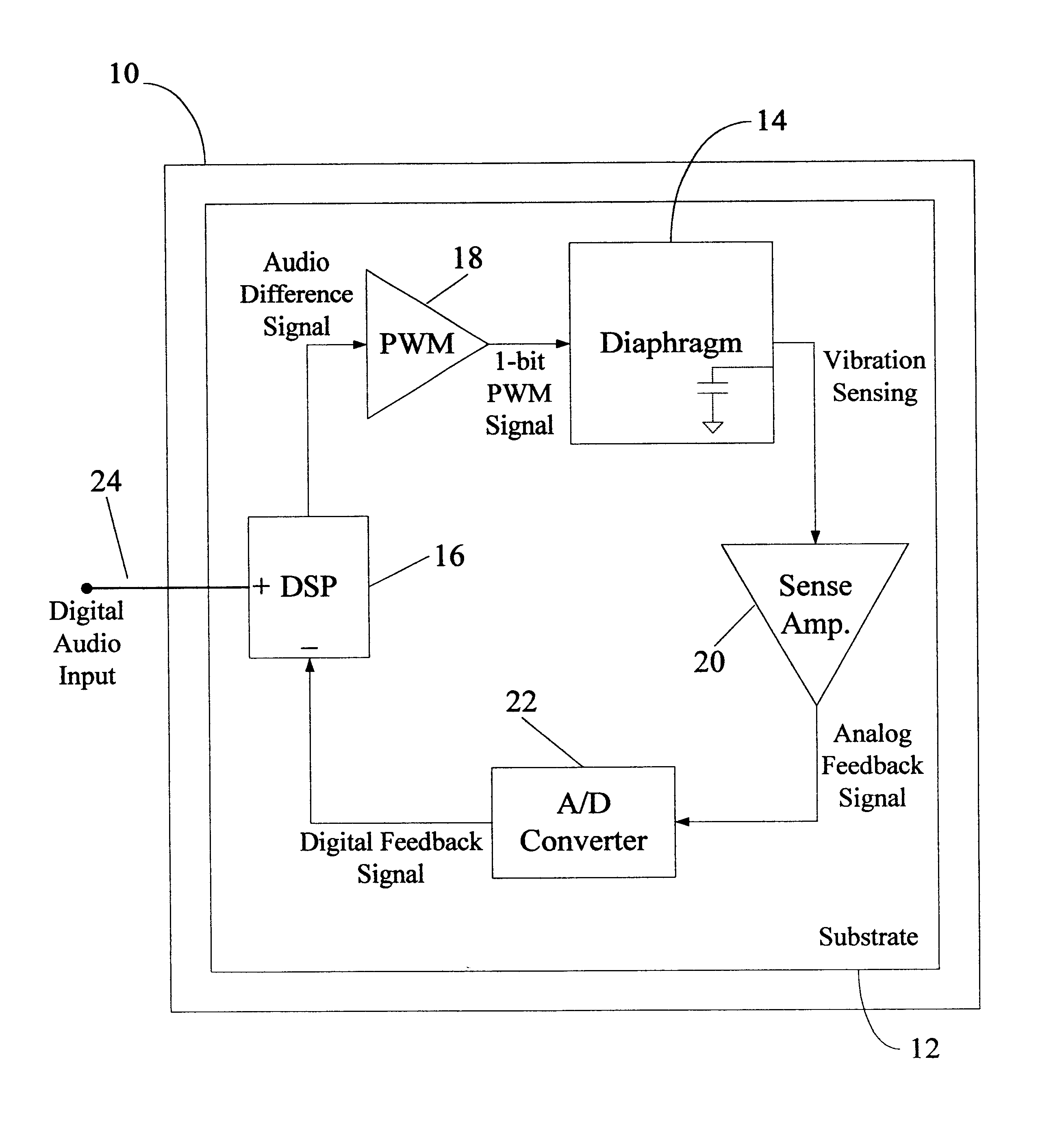
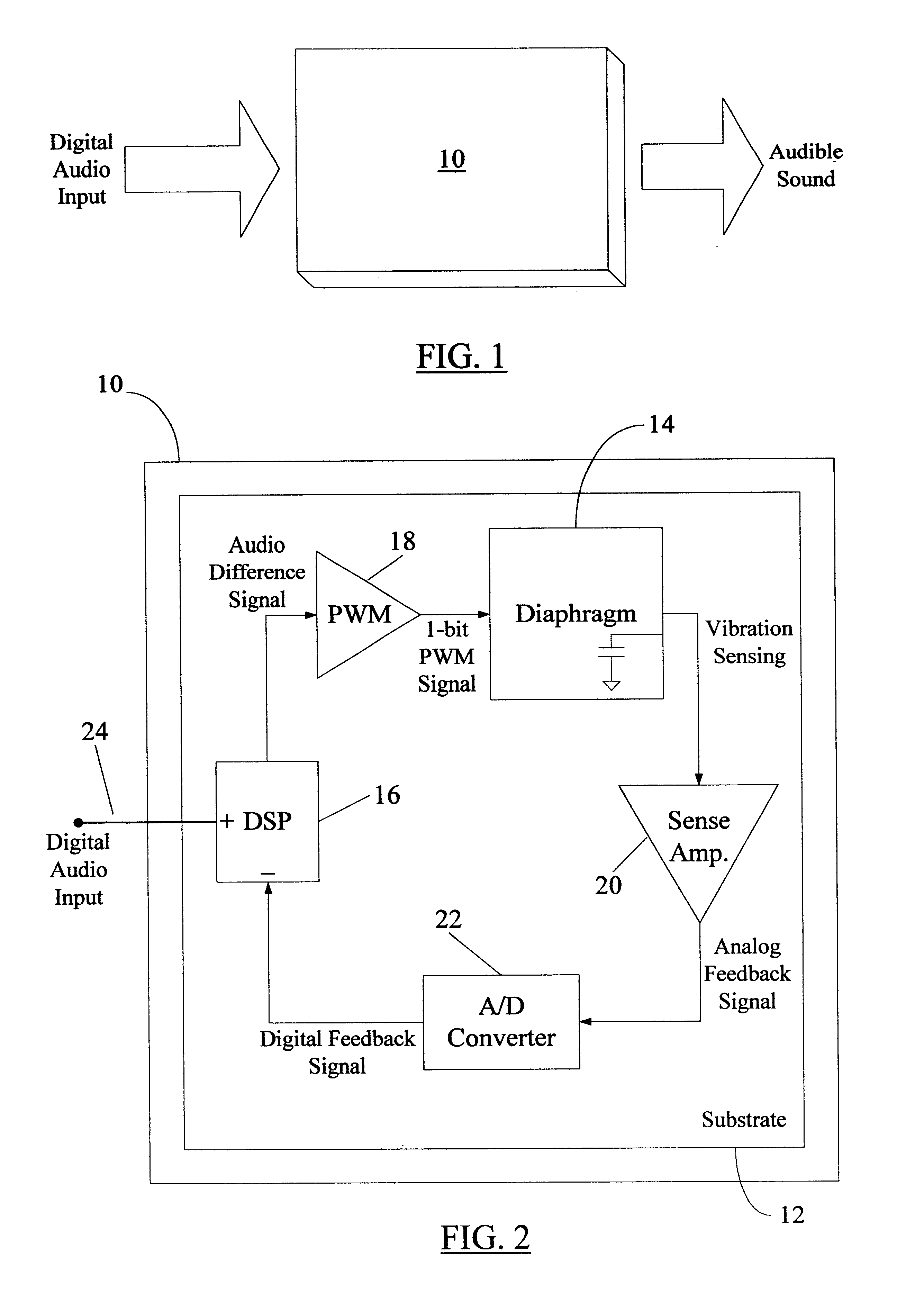
Referring now to FIG. 1, a housing 10 encapsulating circuit elements of an acoustic transducer according to the present invention is shown. In the embodiment of FIG. 1, the acoustic transducer included within the housing 10 is a microspeaker unit that converts the received digital audio input into audible sound. As discussed later, the microspeaker in the housing 10 generates audible sound directly from the digital audio input, which may be from any audio source, e.g., a compact disc player. In one embodiment, the microspeaker in the housing 10 is configured to receive analog audio input (instead of the digital input shown in FIG. 1) and to generate the audible sound from that analog input. In an alternative embodiment (not shown in FIG. 1), the housing 10 may encapsulate a microphone unit that receives sound waves and converts them into electrical signals. The output from the housing 10 in that case may be in analog or digital form as desired by the circuit designer.

Turning now to ...


PUM


Abstract

An acoustic transducer comprising a substrate; and a diaphragm formed by depositing a micromachined membrane onto the substrate. The diaphragm is formed as a single silicon chip using a CMOS MEMS (microelectromechanical systems) semiconductor fabrication process. The curling of the diaphragm during fabrication is reduced by depositing the micromachined membrane for the diaphragm in a serpentine-spring configuration with alternating longer and shorter arms. As a microspeaker, the acoustic transducer of the present invention converts a digital audio input signal directly into a sound wave, resulting in a very high quality sound reproduction at a lower cost of production in comparison to conventional acoustic transducers. The micromachined diaphragm may also be used in microphone applications.

Description

I. CROSS REFERENCE TO RELATED APPLICATIONS(Not Applicable)II. STATEMENT REGARDING FEDERALLY SPONSORED RESEARCH OR DEVELOPMENT(Not Applicable)III. BACKGROUND OF THE INVENTION1. Field of the InventionThe present invention broadly relates to acoustic transducers and, more particularly, to a digital audio transducer constructed using microelectromechanical systems (MEMS) technology.2. Description of the Related ArtElectroacoustic transducers convert sound waves into electrical signals and vice versa. Some commonly known electroacoustic or audio transducers include microphones and loudspeakers, which find numerous applications in all facets of modern electronic communication. For example, a telephone handset includes both, a microphone and a speaker, to enable the user to talk and listen to the calling party. A typical microphone is an electromechanical transducer that converts changes in the air pressure in its vicinity into corresponding changes in an electrical signal at its output. A...

Claims


Application Information

Patent Timeline
IPC IPC(8): H04R17/00B81B3/00B81B7/02H04R1/00H04R3/00H04R19/00H04R23/00
CPCH04R19/005H04R17/00
Inventor LOEB, WAYNE A.NEUMANN, JR., JOHN J.GABRIEL, KAIGHAM J.
Owner CARNEGIE MELLON UNIV
Why Eureka
Try Eureka