
Chemically-enhanced physical vapor deposition

a technology of physical vapor and enhanced vapor, which is applied in the direction of vacuum evaporation coating, plasma technique, coating, etc., can solve the problems of insufficient conformal pvd liners for processes employing very narrow trenches having high aspect ratios, and affecting the quality of the layer

Inactive Publication Date: 2005-01-11
NOVELLUS SYSTEMS
View PDF4 Cites 46 Cited by
  • Summary
  • Abstract
  • Description
  • Claims
  • Application Information

AI Technical Summary

Benefits of technology

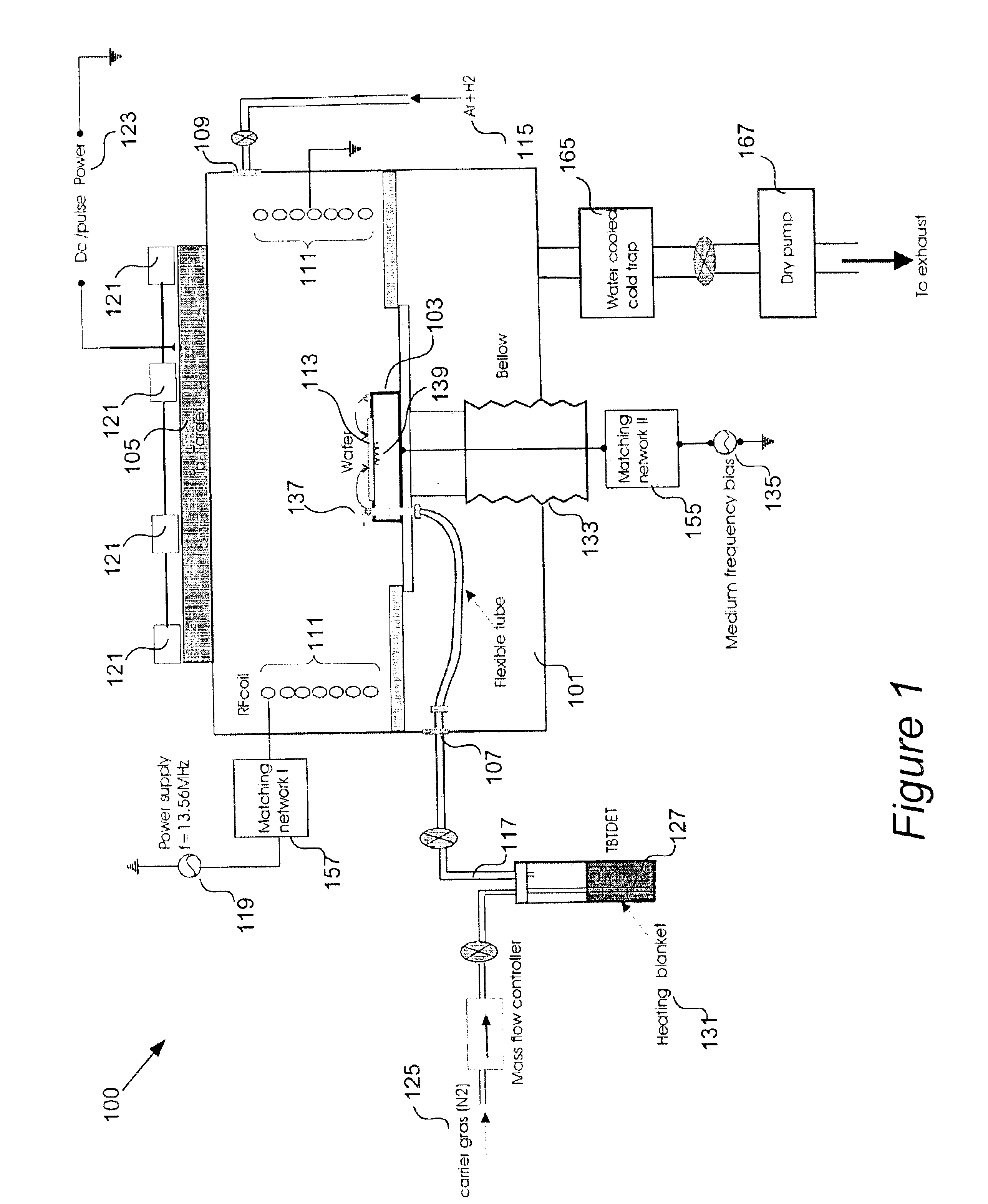
The process chamber will require some source of metal. Frequently, this is a sputter target, comprising one or more of copper, a copper alloy, titanium, cobalt, tungsten, tantalum, ruthenium, and nitrides of these. The process chamber may include various additional features. One example is a temperature controller for controlling the bulk temperature of the substrate. Another

Problems solved by technology

The challenge is particularly great in damascene processes and other processes where the liner must conformally cover high aspect ratio sub-0.5 micrometer scale trenches, vias, or other recesses.
Current film deposition processes have difficulty meeting all these requirements.
But PVD liners are insufficiently conformal for processes employing very narrow trenches having high aspect ratios.
Chemical vapor deposition and atomic layer deposition can produce superbly conformal layers, but those layers are often hampered by impurities and poor morphology—frequently resulting from organic decomposition products of chemical vapor deposition precursors.
The relatively high resistivity of chemical vapor deposition films is a significant downside.
Further, the relatively high process temperatures employed with CVD can limit its application.

Method used


Image

  • Chemically-enhanced physical vapor deposition

Examples


example

Films have been deposited using an apparatus having features similar to those depicted in FIG. 1 and described above. The target was tantalum and a reactive nitrogen carrier gas was employed to deliver TBTDET directly to a silicon dioxide wafer. An RF powered secondary ionization plasma was employed at a power of 300 watts. The magnetron power applied to the target was 2.18 kilowatts. The substrate was held at a temperature of 310 degrees C. and no bias was applied to it. The overall chamber pressure was approximately 150 mTorr. Molecular hydrogen was delivered via the sputtering inlet at a flow rate of about 2 sccm. Molecular nitrogen carrier gas was bubbled through the TBTDET and entered the chamber through a second inlet next to the wafer at a flow rate of about 8 sccm. The bubbler temperature was maintained at a temperature of 120 degrees C.

In the experiment, a planar film was deposited to a thickness of 1150 nanometers on the silicon dioxide wafer. The deposition rate was 38.3 ...


PUM

PropertyMeasurementUnit
Fractionaaaaaaaaaa
Fractionaaaaaaaaaa
Poweraaaaaaaaaa

Abstract

A process merges chemical vapor deposition and physical vapor deposition technologies. It allows physical and chemical vapor deposition to occur in the same process chamber, contemporaneously. The “physical” component involves creation of ionized metal atoms. Ionization is typically accomplished via a plasma within the chamber. If the metal vapor is generated by sputtering, a separate plasma generation mechanism may be employed, which is different from the mechanism employed to generate a “source plasma” for generating sputtering species (e.g., argon ions). Alternatively, a single plasma source may be employed to generate the sputtering species and provide additional ionization of the metal vapor, as is the case with hollow cathode magnetron chambers. In some cases, the CVD precursor is introduced through a first line into the process chamber, while a sputtering gas is introduced via a second line.

Description

BACKGROUNDLiner deposition is a necessary unit operation in integrated circuit fabrication. “Liners” include diffusion barrier layers, seed layers, capping layers, and the like. They are made from metal-containing compounds or metals themselves, such as copper, tungsten, tantalum, titanium, and nitrides of these. As device features shrink well below the 0.5 micrometer scale, there is little room for imperfection in the deposited liners. The challenge is particularly great in damascene processes and other processes where the liner must conformally cover high aspect ratio sub-0.5 micrometer scale trenches, vias, or other recesses. Not only must the liner conformally cover the recess, but it must also adhere well to the underlying dielectric or other support material, be relatively free of impurities and, for many applications, have a stable crystallographic morphology. In cases where the liner carries part of the electrical current flowing in the interconnect, low electrical resistanc...

Claims


Application Information

Patent Timeline
IPC IPC(8): C23C14/32C23C14/00C23C14/14C23C14/22C23C14/34C23C14/35C23C16/06C23C16/50C23C16/517
CPCC23C14/0036C23C14/14C23C14/22C23C14/345H01J37/321C23C16/06C23C16/50C23C16/517C23C14/358
Inventor RUZIC, DAVID
Owner NOVELLUS SYSTEMS
Learn More