
Vertical color filter sensor group with non-sensor filter and method for fabricating such a sensor group

Inactive Publication Date: 2005-01-11
FOVEON
View PDF14 Cites 114 Cited by
  • Summary
  • Abstract
  • Description
  • Claims
  • Application Information

AI Technical Summary

Problems solved by technology

Such sensors have the disadvantage of occupying a relatively large area per resolution element as these sensors are tiled together in a plane.
In addition, reconstruction of a color image from such a sensor array is computationally intensive and often results in images with artifacts, defects, or inferior resolution.
The device disclosed in the Carr patent has several shortcomings, the most notable being its large area, rendering it unsuitable for the image sensor density requirements of modern imaging systems.
The technology employed for contact formation to the buried infrared sensing diode is not suitable for modern imaging technology or extension to a 3-color sensor.
This requirement disadvantageously increases sensor area and complicates support circuits in detectors that include the sensor groups.
The added circuit complexity makes it difficult to make an image sensor array that has flexible color readout capabilities (as disclosed herein) and makes it impossible to achieve the small sensor size required by many modern electronic imaging applications.
Among the shortcomings of this sensor are difficult and non-standard manufacturing techniques, use of structures that prohibit high density of sensors (in an array), no ability to select different colors for read out, and inability to perform detection of three or more colors using a monolithic semiconductor substrate.
The performance of an array of such sensors is limited by the poor color response of the double-junction photodiode and by the fact that the n-well forms the cathode of both photodiodes, making the sensor design very susceptible to non-linear crosstalk between the color channels.
Additionally, the authors cite non-uniformity and process / fabrication constraints that limit the performance and potential benefits of this design.
In contrast, time sequential photon sensing methods do not perform photon sensing at the same time for all wavelength bands.

Method used


Image

  • Vertical color filter sensor group with non-sensor filter and method for fabricating such a sensor group
  • Vertical color filter sensor group with non-sensor filter and method for fabricating such a sensor group
  • Vertical color filter sensor group with non-sensor filter and method for fabricating such a sensor group

Examples


Embodiment Construction

rmed during a subsequent stage of the multi-stage implantation process) whose bottom portion is shown in both FIGS. 18 and 18A.

[0052]FIG. 19 is a graph of the mask thickness required during typical implantation of Boron, Phosphorus, Arsenic, and Antimony, for each of five indicated masking materials.

[0053]FIG. 20 is a simplified cross-sectional view (in a vertical plane) of an embodiment of the inventive VCF sensor group including a blanket barrier layer (205) between two sensors.

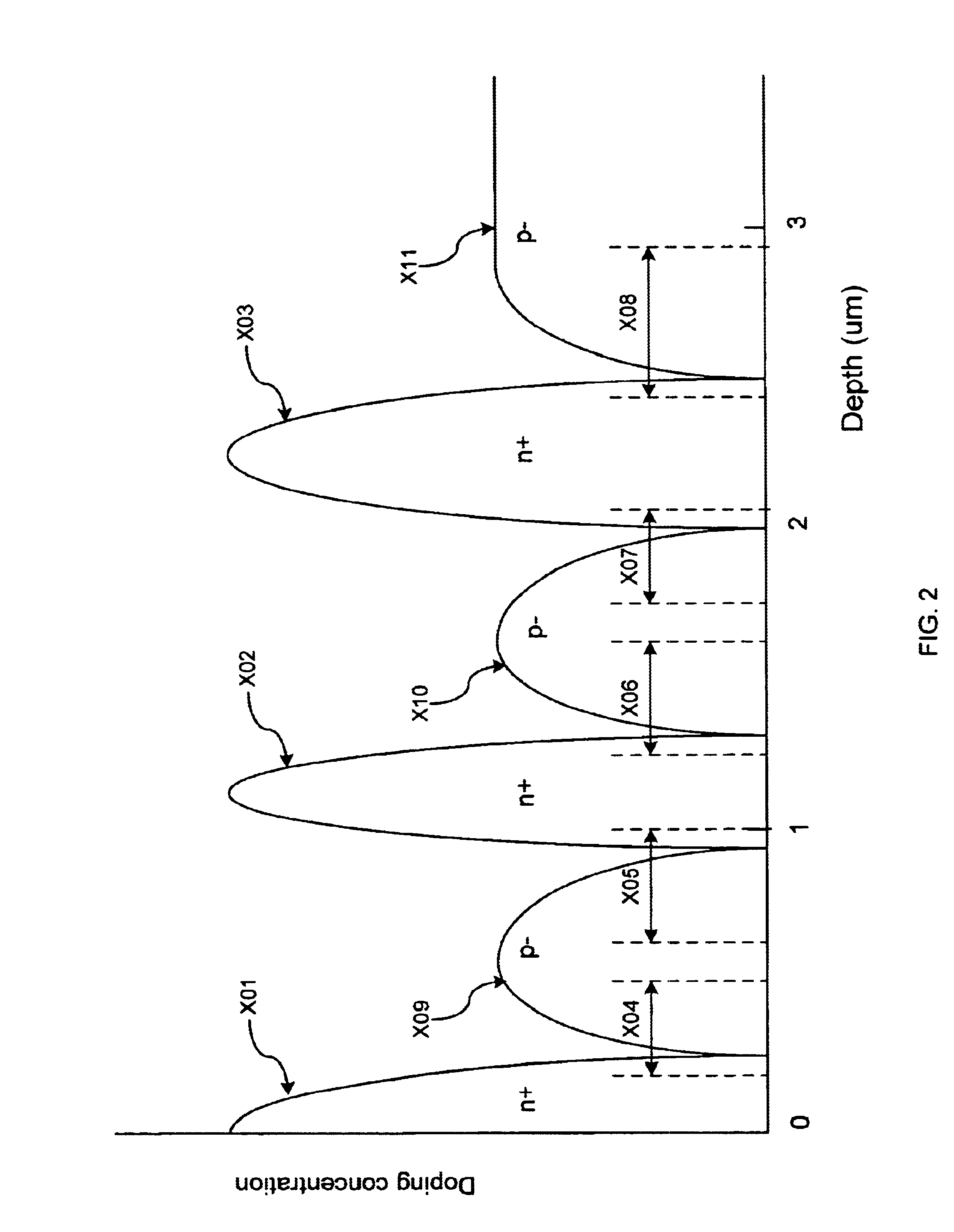
[0054]FIG. 21 is a graph of dopant concentration as a function of depth in the sensor group of FIG. 20.

[0055]FIG. 22 is a simplified cross-sectional view (in a vertical plane) of a variation on the sensor group of FIG. 20, including conventional blanket barrier implants rather than the inventive blanket barrier layer 205.

[0056]FIG. 23 is a graph of dopant concentration as a function of depth in the sensor group of FIG. 22.

[0057]FIG. 24 is a simplified cross-sectional view (in a vertical plane) of another em...


PUM


Abstract

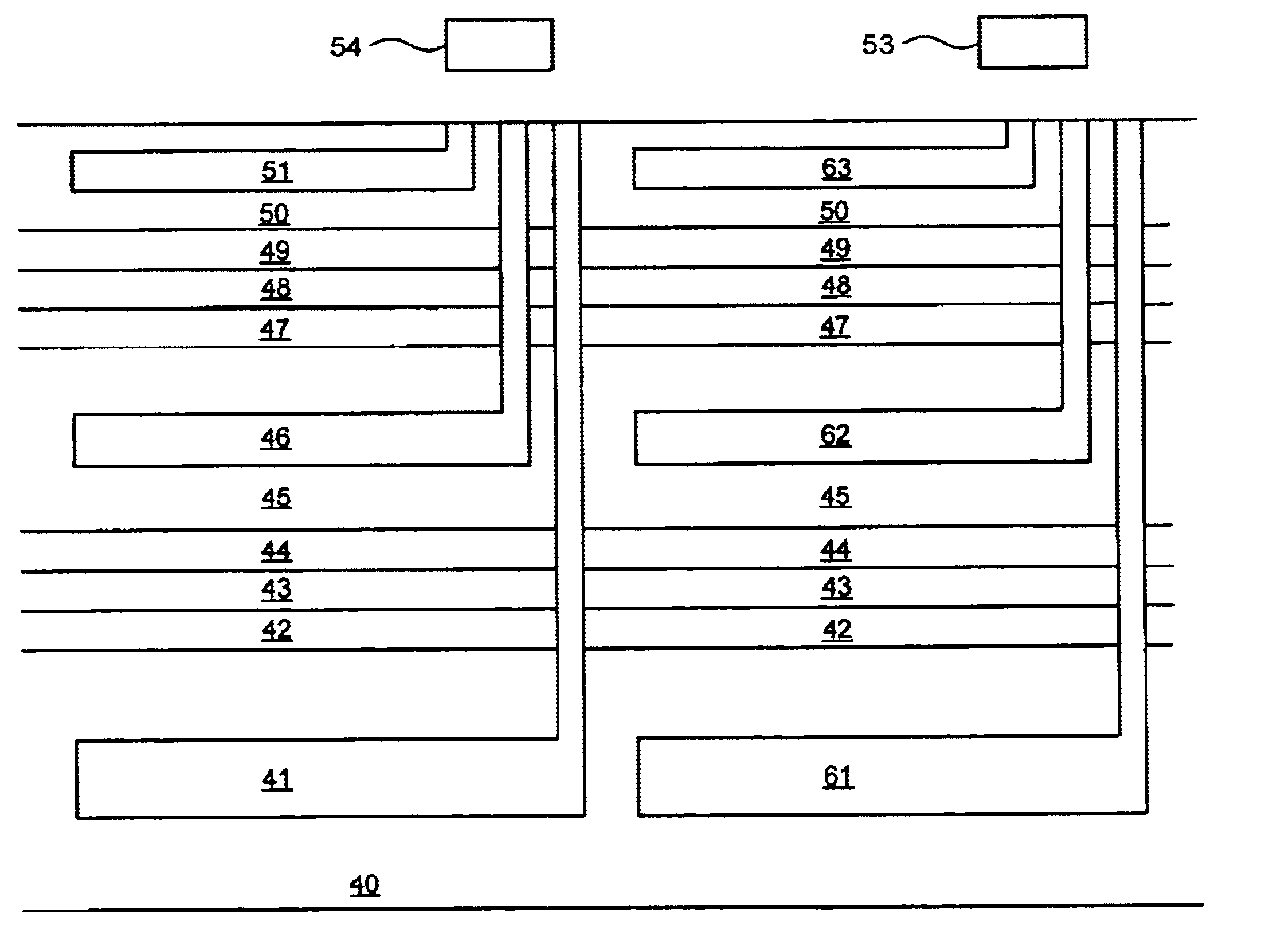
A vertical color filter sensor group formed on a substrate (preferably a semiconductor substrate) and including at least two vertically stacked, photosensitive sensors. In preferred embodiments, the sensor group includes at least one filter positioned relative to the sensors such that radiation that has propagated through or reflected from the filter will propagate into at least one sensor. Preferably, the filter is or includes a layer that has been integrated with the sensors by a semiconductor integrated circuit fabrication process. In other embodiments, the sensor group includes a micro-lens. Other aspects of the invention are arrays of vertical color filter sensor groups, some or all of which include at least one filter or micro-lens, and methods for fabricating vertical color filter sensor groups and arrays thereof.

Description

RELATED APPLICATIONS[0002]This application is a continuation in part of U.S. patent application Ser. No. 10 / 103,304, entitled VERTICAL COLOR FILTER DETECTOR GROUP AND ARRAY, filed on Mar. 20, 2002.BACKGROUND OF THE INVENTION[0003]1. Field of the Invention[0004]The present invention relates to photosensitive sensor groups that comprise vertically stacked sensors. In each group, semiconductor material chromatically filters incident electromagnetic radiation vertically (optionally, other material also filters the radiation) and each sensor simultaneously detects a different wavelength band. The invention also relates to arrays of such sensor groups, with each sensor group positioned at a different pixel location.[0005]2. Background of the Invention[0006]The expressions “filter” and “color filter” are used interchangeably herein (including in the claims) in a broad sense to denote an element that selectively transmits or reflects at least one wavelength band of electromagnetic radiation...

Claims


Application Information

Patent Timeline
IPC IPC(8): H01L21/00H01L31/101H01L31/113H01L33/00H01L27/146H01L27/148H01L31/00H01L31/0216H01L31/107
CPCH01L27/14603H01L27/14621H01L27/14647H01L27/14687H01L31/02162H01L27/14623H01L31/107H01L27/14627
Inventor MERRILL, RICHARD B.LYON, RICHARD F.TURNER, RICHARD M.HANNEBAUER, ROBERT S.MARTIN, RUSSEL A.
Owner FOVEON
Learn More