Process and catalyst for reducing nitrogen oxides

a technology of nitrogen oxides and catalysts, which is applied in the direction of nitrogen purification/separation, inorganic chemistry, exhaust treatment, etc., can solve the problems of toxic vanadium compounds at elevated exhaust gas temperatures, high catalyst activity, and high catalyst age, so as to reduce improve the activity of reduction catalysts , the effect of reducing the age of catalysts

Inactive Publication Date: 2005-01-18
UMICORE AG & CO KG
View PDF11 Cites 77 Cited by
  • Summary
  • Abstract
  • Description
  • Claims
  • Application Information

AI Technical Summary

Benefits of technology

It has been shown that an increase in the nitrogen dioxide content in the exhaust gas greatly improves the activity of the reduction catalysts mentioned and also decreases ageing of the catalysts. In addition, nitrogen dioxide also increases in particular the activity of the catalysts at low temperatures. It is suspected that this positive effect of nitrogen dioxide is based on the fact that, for example, the divalent copper ions in the catalyst are reduced to monovalent copper ions due to selective catalytic reduction, which means that their catalytic activity is reduced. As a result of the oxidative components present in the exhaust gas, such as oxygen and nitrogen dioxide, the copper ions are reoxidized to divalent copper ions and thus recover their original activity. Nitrogen dioxide acts in a particularly advantageous manner here due to its relatively high oxidizing capacity. This reaction principle applies to all SCR-active transition metal ions which permit this type of valency change. This includes the ions of vanadium, chromium, iron, nickel, copper, cerium, praseodymium and terbium. Ions of iron, copper and cerium are particularly suitable.

Problems solved by technology

Known SCR-catalysts have the disadvantage that their catalytic activity is not high enough for the high space velocities prevailing in the case of car exhaust gas treatment and is subject to rapid ageing.
One problem associated with the V2O5 / WO3 / TiO2 catalysts usually used in the power station sector is the possible emission of volatile, toxic vanadium compounds at elevated exhaust gas temperatures.
Replacement of these vanadium-containing catalysts by vanadium-free catalysts, for example catalysts based on zeolite exchanged with transition metals such as iron or copper, does not seem to be suitable due to the known low ageing stability of these catalysts.

Method used


Image

  • Process and catalyst for reducing nitrogen oxides
  • Process and catalyst for reducing nitrogen oxides
  • Process and catalyst for reducing nitrogen oxides

Examples


example

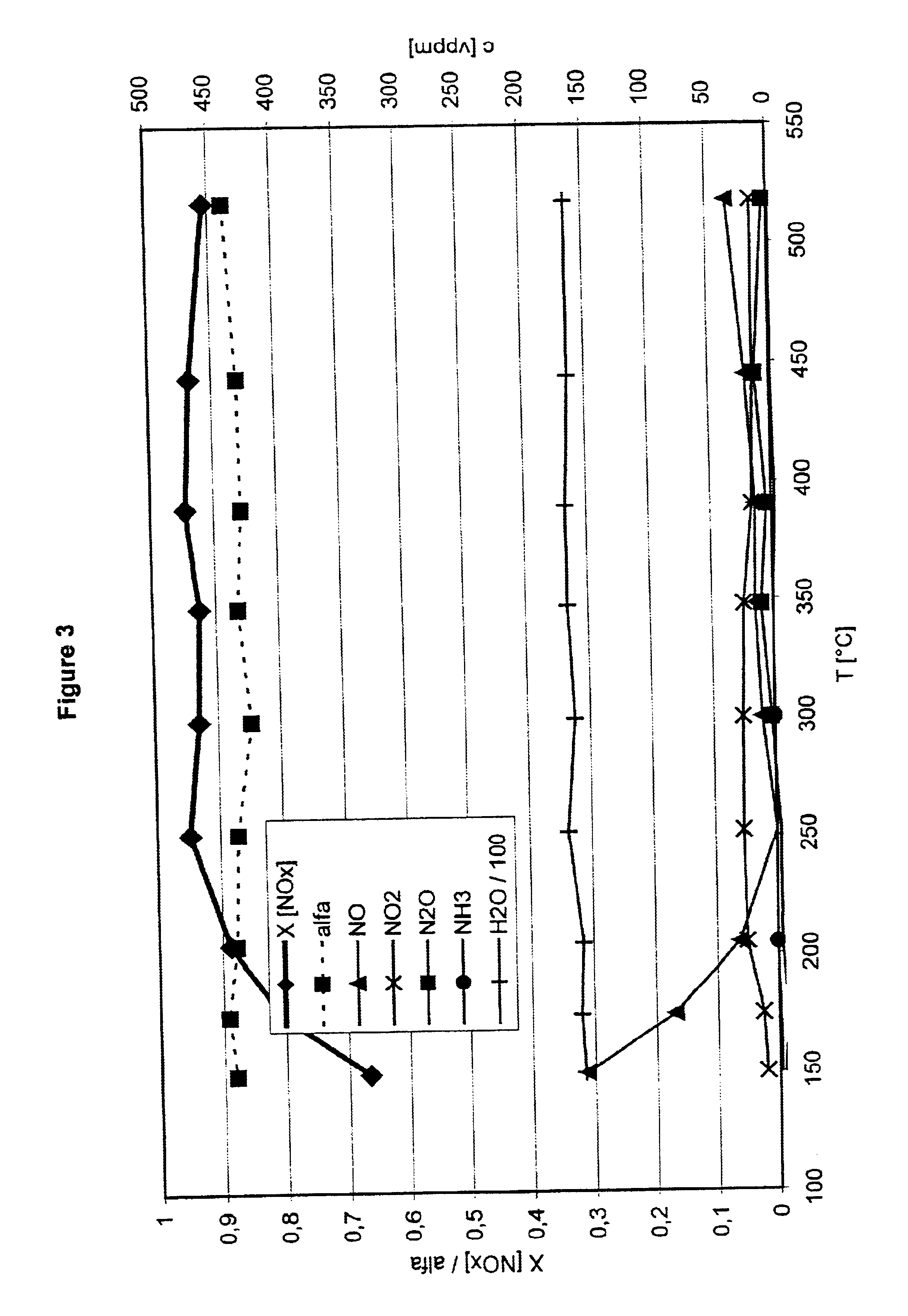
Drilled cores of these catalysts with a diameter of 2.54 cm and a length of 7.62 cm were subjected to the following synthesis gas mixture at a space velocity of 30000 h−1 to test them in the process according to the invention:

500Vol. ppm nitrogen oxides in the ratio NO:NO2 of 1:1;3:1 and 1:3450Vol. ppm ammonia5Vol. % oxygen1.3Vol. % water vapourRemainder, nitrogen

The temperature of the synthesis gas was increased in steps from 150 to 525° C. For each temperature step, the gas composition was analysed downstream of the reduction catalyst.

FIG. 3 gives the results for a freshly prepared catalyst. The volume ratio NO / NO2 in this case was 1:1.

FIGS. 4 to 6 show the experimental results for aged catalysts. To age the catalysts, they were stored for a period of 48 hours under hydrothermal conditions at a temperature of 650° C.

FIG. 4 shows the results for a volume ratio NO / NO2 of 3:1, FIG. 5 for a volume ratio NO / NO2 of 1:1 and FIG. 6 for a volume ratio NO / NO2 of 1:3. As can be seen from the...


PUM

PropertyMeasurementUnit
temperaturesaaaaaaaaaa
concentrationaaaaaaaaaa

Abstract

A process for reducing the nitrogen oxides present in a lean exhaust gas from an internal combustion engine by selective catalytic reduction on a reduction catalyst using ammonia, wherein a fraction of the nitrogen monoxide present in the exhaust gas is oxidized to nitrogen dioxide before the exhaust gas, together with ammonia, is passed over the reduction catalyst. The reduction catalyst contains a zeolite exchanged with transition metals and oxidation of the nitrogen monoxide is performed in such a way that the exhaust gas contains 30 to 70 vol. % of nitrogen dioxide before contact with the reduction catalyst.

Description

INTRODUCTION AND BACKGROUNDThe present invention relates to a process for reducing the nitrogen oxides present in a lean exhaust gas produced from an internal combustion engine by selective catalytic reduction on a reduction catalyst using ammonia, wherein a fraction of the nitrogen monoxide present in the exhaust gas is oxidized to nitrogen dioxide before the exhaust gas, together with ammonia, is passed over the reduction catalyst.The process of selective catalytic reduction (SCR=selective catalytic reduction) has been used for a long time in the power station sector to reduce the nitrogen oxides present in the flue gases from a power station. The flue gases from power stations have a net oxidizing effect due to the high proportion of oxygen. The nitrogen oxides present therein can therefore be reduced to nitrogen only with difficulty. This problem was solved by so-called selective catalytic reduction, in which the flue gas is mixed with ammonia and passed over a suitable reductio...

Claims


Application Information

Patent Timeline
Patent Type & Authority Patents(United States)
IPC IPC(8): B01D53/94B01J29/00B01J29/46B01J29/072B01J37/00B01J37/02F01N3/20B01J35/00B01J35/04B01D53/34B01D53/56B01D53/74B01D53/86F01N3/08B01J8/02B01J21/00B01J23/80B01J29/06B01J29/064B01J29/076B01J37/30C01B21/00C01B21/04F01N3/10F01N3/28
CPCB01D53/9418B01J29/072B01J29/46B01J37/0215F01N3/2066B01D53/9477Y02T10/24B01D2251/2067B01D2255/2065B01D2255/20738B01D2255/20761B01D2255/504B01D2255/808B01J35/04F01N2610/02Y02T10/12
Inventor SCHAFER-SINDLINGER, ADOLFPFEIFER, MARCUSSPURK, PAULDEMEL, YVONNEKREUZER, THOMASLOX, EGBERT
Owner UMICORE AG & CO KG
Why Eureka
Try Eureka