Optical recording medium and optical recording method

a recording medium and optical recording technology, applied in the field of optical recording medium and optical recording method, can solve the problems of insufficient erase characteristic, complicated material preparation procedure, small signal amount of birefringence, etc., and achieve the effect of high-density recording and increased orientation degr

Inactive Publication Date: 2005-01-18
SONY CORP +1
View PDF7 Cites 0 Cited by
  • Summary
  • Abstract
  • Description
  • Claims
  • Application Information

AI Technical Summary

Benefits of technology

Moreover, even when the light orientation film has a low orientation degree, the liquid crystal thin film has a high orientation degree, thereby enabling to obtain an orientation degree increase effect.
Furthermore, the greatest effect of the present invention is that it is possible to perform recording / reproducing with a same wavelength which has been impossible in the case of a single light orientation film layer. Since it is possible to perform recording / reproducing using a blue light source, it is possible to obtain a high-density recording. The blue light source is also appropriate as an excitation light of fluorescence.
Moreover, since the materials used in this invention are all organic materials, they can be burnt down without leaving a harmful substance. This is a great advantage as compared to the magneto-optical recording medium and the phase change recording medium which are now widely used as the rewritable optical recording medium, because ecology is also a great industrial problem.

Problems solved by technology

This results in a small signal amount of the birefringence.
However, the material preparation procedure is complicated, which is a problem for a mass production, and the erase characteristic is not sufficient.
Moreover, in general, such light orientation organic films also have a problem in thermal stability and in stability against light irradiation and still cannot be used in practice.
However, in an optical disc, light is also irradiated during reproducing and the reproducing light changes the molecule orientation direction, causing a problem that recorded information is lost.
In general, the ratio of the reproducing light and the recording light is about 1:10, and it is difficult to provide a greater difference because of the limit in the laser capability.
However, according to this method two light sources having different wavelength values should be contained in one apparatus, which increases the apparatus size and cost.

Method used


Image

  • Optical recording medium and optical recording method
  • Optical recording medium and optical recording method
  • Optical recording medium and optical recording method

Examples


Embodiment Construction

Description will now be directed to the optical recording medium and the optical recording method according to the present invention with reference to the attached drawings.

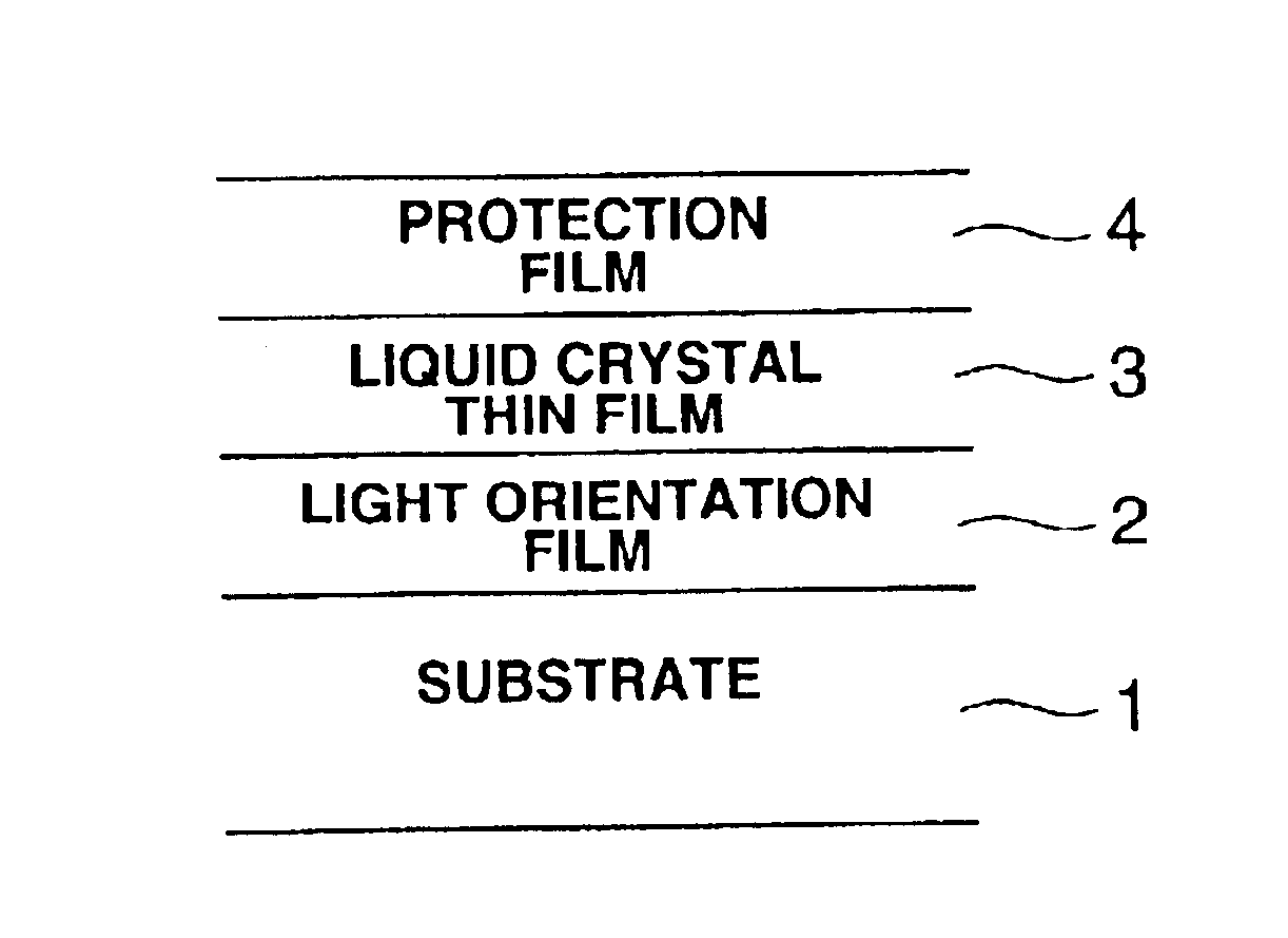
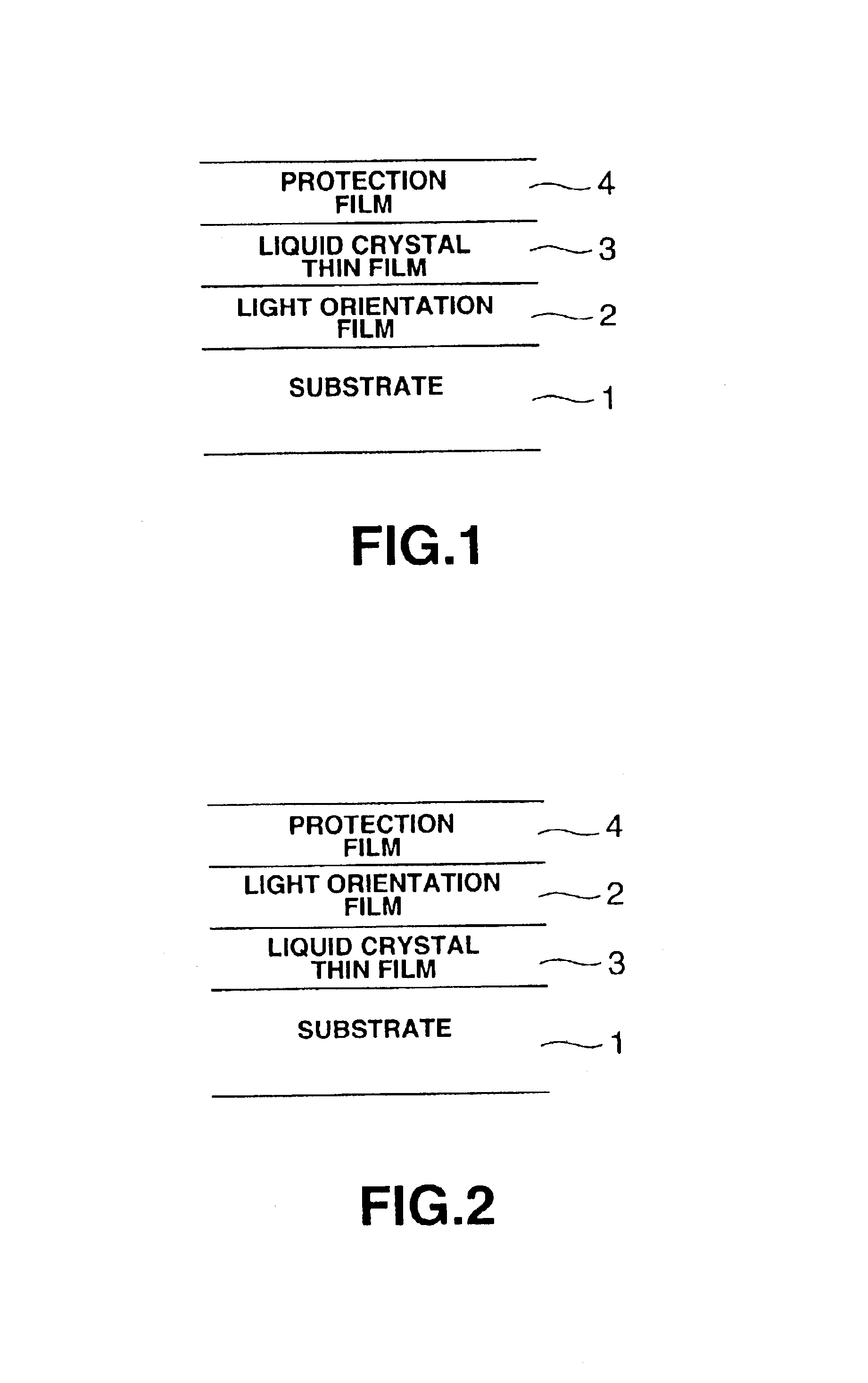
Firstly, FIG. 1 shows a basic configuration of the optical recording medium according to the present invention.

The optical recording medium shown in FIG. 1 includes a light orientation film 2 and a liquid crystal thin film 3 which are successively formed on a substrate 1 and covered with a protection film 4, so that recording light and reproducing light are irradiated from the side of the substrate 1.

Alternatively, as shown in FIG. 2, it is also possible to successively form the liquid crystal orientation film 3 and the light orientation film 2 in this order on the substrate 1, so that recording light and reproducing light are irradiated from the side of the substrate 1.

Here, the light orientation film 2 utilizes the photoisomerization reaction by, for example, azobenzene. The azobenzene has a structure shown in ...


PUM

PropertyMeasurementUnit
thicknessaaaaaaaaaa
thicknessaaaaaaaaaa
thicknessaaaaaaaaaa

Abstract

A light orientation film and a liquid crystal thin film are formed adjacent to each other. Light is irradiated to the light orientation film and the liquid crystal thin film, so as to cause the light orientation film to be orientated while viscosity of the liquid crystal thin film is lowered by a temperature increase by the light irradiation, so that an intermolecular force on the boundary between the light orientation film and the liquid crystal thin film causes the liquid crystal molecules in the liquid crystal thin film to the orientation of the light orientation film. By this orientation of the liquid crystal molecules, recording information is maintained. Thus, it is possible to realize a sufficient signal amount while using the light orientation film as well as to obtain a thermal stability and a stability against light irradiation.

Description

BACKGROUND OF THE INVENTIONThe present invention relates to a novel optical recording medium having a light orientation film in combination with a liquid crystal thin film and to an optical recording method.BACKGROUND ARTRecently, research is widely made on application of a light orientation organic film using azobenzene as a recording material of an optical disc, for example.An optical disc using a light orientation organic film is entirely made from an organic material and can be burnt down without leaving a harmful substance. This is a great advantage as compared to a magneto-optical medium and a phase-change recording medium which are now widely used as a rewritable optical recording medium, because ecology is also a great industrial problem.A signal detection when the aforementioned light orientation organic film on an optical disc is based on a method for reading a birefringence caused when azobenzene is orientated.However, the birefringence of the light orientation organic fi...

Claims


Application Information

Patent Timeline
Patent Type & Authority Patents(United States)
IPC IPC(8): G02F1/133G02F1/1337G02F1/13G11B7/25G11B7/24G11B7/257G02F1/1347G11B7/244G11B7/00G11B7/0045G11B7/2403G11B7/24038G11B7/253G11B7/2534G11B7/258G11B7/2585G11B7/259
CPCG02F1/132G02F1/133788G02F1/13762G11B7/0045G11B7/2403G11B7/25G11B7/252G02F1/133362G11B2007/25715G11B7/24038G11B7/245G11B7/2534G11B7/2585G11B7/259G11B2007/0013G11B2007/2571G11B2007/25713B41M5/281
Inventor SABI, YUICHIYASUDA, AKIOYAMAMOTO, MASANOBUNEHER, DIETER
Owner SONY CORP
Why Eureka
Try Eureka