Control of an optical fiber scanner

a control and optical fiber technology, applied in the direction of instruments, optical elements, applications, etc., can solve the problems of limiting the application of optical scanning for small size, large amplitudes or large angular deflections at the fiber's tip when excited into resonance, and large amplitudes or large angular deflections at the fiber's tip, so as to achieve robust cancellation and remove nonlinear behavior

Inactive Publication Date: 2005-01-18
UNIV OF WASHINGTON
View PDF32 Cites 445 Cited by
  • Summary
  • Abstract
  • Description
  • Claims
  • Application Information

AI Technical Summary

Benefits of technology

Still another aspect of the present invention is directed to a method for controlling an optical scanner. The method includes steps generally consistent with the functions of the elements comprising the controls discussed above. One preferred form of the method includes the step of producing the drive signal for driving the optical scanner in regard to a first axis and a second axis, where the second axis is generally orthogonal to the first axis. The drive signal produces a desired movement of the optical scanner about only one of the first and the second axes, but includes a component acting

Problems solved by technology

The combination of an optical fiber's low mass, low moment of inertia, and light damping results in large amplitudes or large angular deflections at its tip when excited into resonance.
Small movements of the actuator at the base of an optical fiber (base excitation) or weak forces produced by the actuator either along the length of the fiber or at its tip, efficiently result in large amplitudes or large angular deflections at the fiber's tip.
Combining both high resolution (>100,000 pixels) and wide FOV (>30°) in a single display is a difficult technical challenge, limiting the application of optical scanning for small size, low cost optical scanners that have both high resolution and wide FOV.
To date, a mirror-based resonant scanner fabricated as a micro-electromechanical systems (MEMS) device has yet to be demonstrated as a viable method for manufacturing low cost optical scanners for visual displays of wide FOV and at video scan rates.
Moreover, there is a commercial need for low cost, large-scale (panoramic) optical displays, because larger CRT displays are uneconomical in energy and space.
Finally, the lack of low cost micro-

Method used


Image

  • Control of an optical fiber scanner
  • Control of an optical fiber scanner
  • Control of an optical fiber scanner

Examples


Embodiment Construction

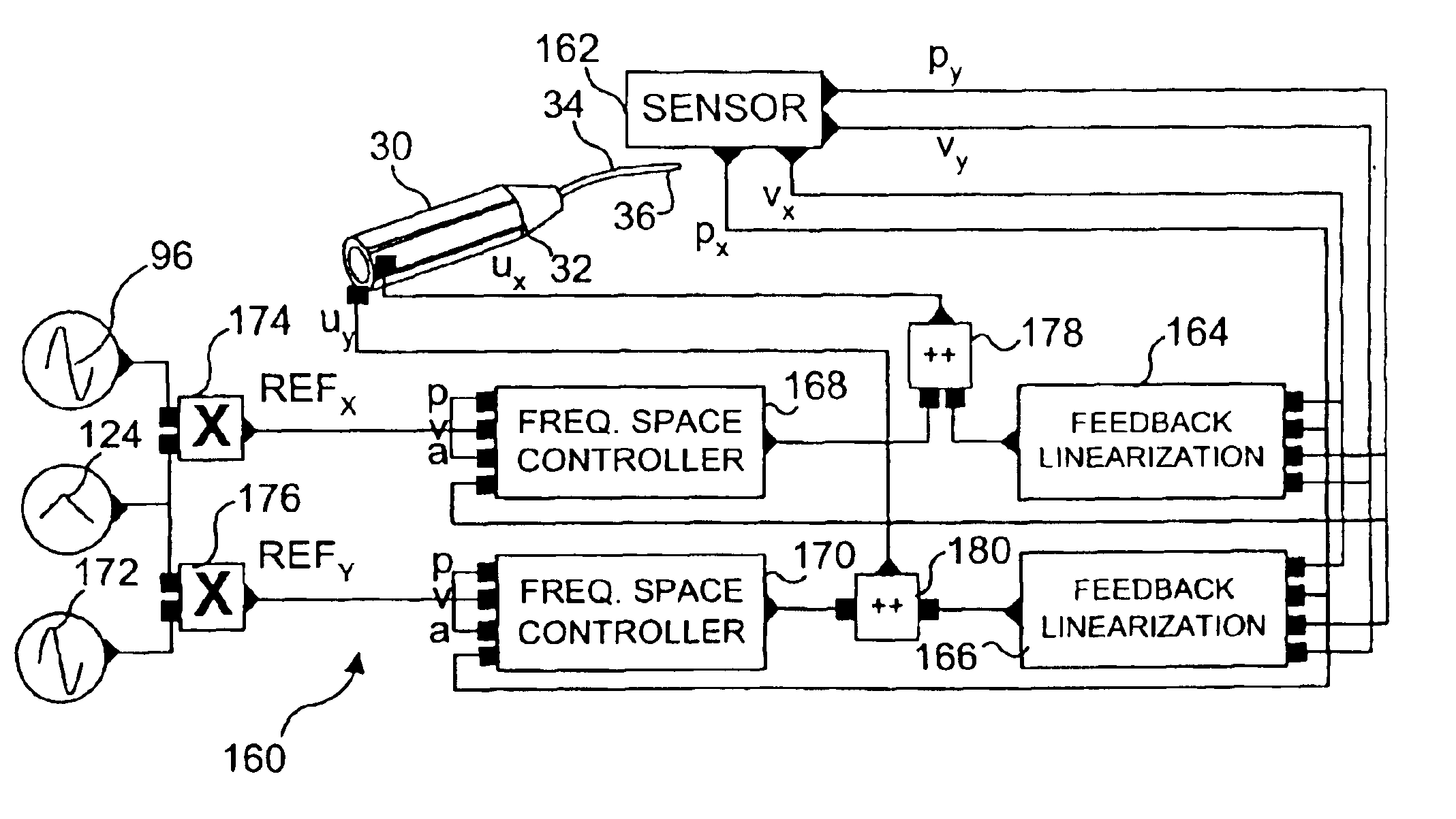
The present invention is directed to controlling cantilevered light guides used in a many different applications. While it should be clearly understood that the present invention is not limited to controlling just an optical fiber, an initial application of the present invention for that purpose provides a disclosure of several different embodiments of exemplary controls that are used in connection with controlling the drive signal applied to cause an optical fiber to move in a desired pattern at or near its resonance. However, it is not intended that the discussion of the present invention in connection with controlling the movement of an optical fiber in any way limit its application to that type of light guide.

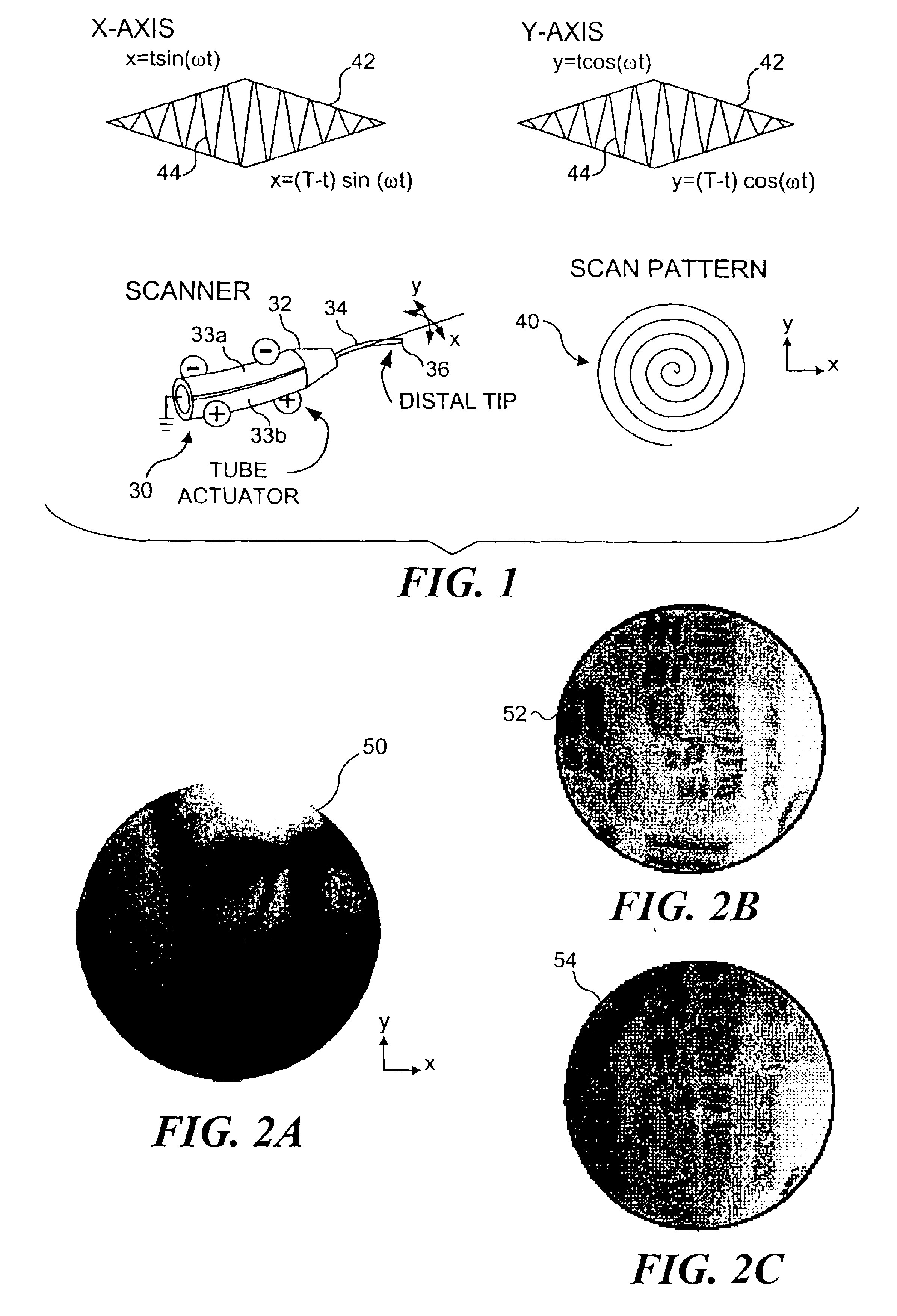
A resonant optical fiber that is controlled by the present invention can be either tapered or non-tapered and can be driven in several scanning patterns, as appropriate for the application of the scanning optical fiber. The following discussion focuses on the control of res...


PUM


Abstract

Controls for an optical scanner, such as a single fiber scanning endoscope (SFSE) that includes a resonating optical fiber and a single photodetector to produce large field of view, high-resolution images. A nonlinear control scheme with feedback linearization is employed in one type of control to accurately produce a desired scan. Open loop and closed loops controllers are applied to the nonlinear optical scanner of the SFSE. A closed loop control (no model) uses either phase locked loop and PID controllers, or a dual-phase lock-in amplifier and two PIDs for each axis controlled. Other forms of the control that employ a model use a frequency space tracking control, an error space tracking control, feedback linearizing controls, an adaptive control, and a sliding mode control.

Description

FIELD OF THE INVENTIONThe present invention generally relates to controls for an optical scanner, and more specifically, to controls for a resonant optical scanner that is used either for image acquisition or display of an image, wherein the controls determine the movement of a cantilevered distal tip of the optical fiber relative to an adjacent surface.BACKGROUND OF THE INVENTIONThe combination of an optical fiber's low mass, low moment of inertia, and light damping results in large amplitudes or large angular deflections at its tip when excited into resonance. Small movements of the actuator at the base of an optical fiber (base excitation) or weak forces produced by the actuator either along the length of the fiber or at its tip, efficiently result in large amplitudes or large angular deflections at the fiber's tip. When driven to move at resonance or near resonance, an optical fiber scanner can be used for image display and acquisition, as well as the basis of several fiber opti...

Claims


Application Information

Patent Timeline
IPC IPC(8): G02B26/10G02B6/26G02B6/35G02B6/32
CPCA61B1/0008A61B1/00172G02B6/262G02B26/10G02B6/3504G02B6/359G02B6/32A61B1/00097
Inventor SMITHWICK, QUINN Y. J.SEIBEL, ERIC J.FAUVER, MARK
Owner UNIV OF WASHINGTON
Why Eureka
Try Eureka