One-piece biocompatible absorbable rivet and pin for use in surgical procedures

a biocompatible, surgical technology, applied in the field of surgical devices, can solve the problems of inconvenient installation, inconvenient handling, and permanent removal of the device, and achieve the effects of convenient installation, convenient handling, and enhanced length

Inactive Publication Date: 2005-01-25
CODMAN & SHURTLEFF INC
View PDF72 Cites 65 Cited by
  • Summary
  • Abstract
  • Description
  • Claims
  • Application Information

AI Technical Summary

Benefits of technology

The invention includes in another aspect a biocompatible bioabsorbable rivet and pin fastener having(1) a biocompatible rivet portion including a head with a proximal end, a distal end and a central axis, the head having an internal passage extending from the proximal to the distal end of the head that is substantially parallel to the central axis of the head, the distal end of the head being mechanically connected to two or more legs that extend generally distally from the head and have an internal surface that faces the central axis, and(2) a biocompatible pin having a radial cross-section that, when inserted into the internal passage of the rivet and advanced from the proximal end toward the distal end of the head of the rivet contacts the internal surface of said legs to force the legs in a direction outwardly from the central axis,wherein the pin is integrally connected with the body by a breakable connection such that the rivet and pin form an elongated single piece assembly for shipping and handling; and driving force directed along the central axis breaks the connection and drives the pin distally into the body to fix the fastener in place. The rivet and pin assembly preferably forms a single coaxial unit of enhanced length that is easily handled, and may be loaded in a driver for convenient installation.

Problems solved by technology

The disadvantage of metal devices is that they are permanent and may need to be removed through a second surgical procedure.
If they remain in the body, tissue atrophy and subsequent loosening of the device may occur.
Such designs are undesirable for surgical applications where only a thin layer of bone is available for attachment or it is not possible to drill beyond the depth of the thin bone layer for fear of damaging underlying soft tissues, such as in cranial and maxillo-facial surgical procedures.
Since carbon fibers are not absorbed by or resorbed within the body, this fastener is only partially absorbable.
Having a solid pin therefore limits the fastening ability of the device since the pin cannot deform if the surround ing bone is so stiff that the legs cannot expand radially outwards.
In such a case where the surrounding bone is stiffer than that for which the device was designed and the pin is solid, the large force required to drive the rigid pin into the tapered hole will be such that either the legs will be deformed and rendered useless or the pin will be crushed.
A number of the above described rivet constructions require specialized tooling for their proper installation, and this may involve two separate tools, or a single tool of relatively complicated construction.
In dealing with the several cooperating parts of the rivet, there is a risk of separation of the components within their packaging prior to use, of dropping one or more components in the surgical wound, or of mis-handling or mis-aligning a component due to the small size of the individual parts.
Further, the multi-component nature of such rivet structures may necessitate installation tooling that is ill adapted for, or incapable of operating to, install plural rivets before requiring reloading.

Method used


Image

  • One-piece biocompatible absorbable rivet and pin for use in surgical procedures
  • One-piece biocompatible absorbable rivet and pin for use in surgical procedures
  • One-piece biocompatible absorbable rivet and pin for use in surgical procedures

Examples


example 1

Synthesis of a 85:15 (mol / mol) oly(lactide-co-glycolide) Copolymer

The method described below and utilized in this example is similar to those described in U.S. Pat. Nos. 4,643,191, 4,653,497, 5,007,923, 5,047,048 which are incorporated by reference, and is known to those skilled in the art.

To a flame dried 500 mL 1-neck round bottom flask equipped with an overhead mechanical stirrer and nitrogen inlet, 268 grams (1.86 moles) of L(-) lactide, 38.4 grams (0.330 moles) of glycolide, 0.53 grams (7×10⁻³ moles) of glycolic acid initiator, and 131 microliters of a 0.33 M solution of stannous octoate catalyst are added.

The assembly is then placed in a high temperature oil bath at 185° C. The stirred monomers quickly begin to melt. The low viscosity melt quickly increases in viscosity. Mechanical stirring of the high viscosity melt is continued for a total reaction time of 4 hours.

The 85:15 (mol / mol) poly(lactide-co-glycolide) copolymer is removed from the bath, cooled to room temperature un...

example 2

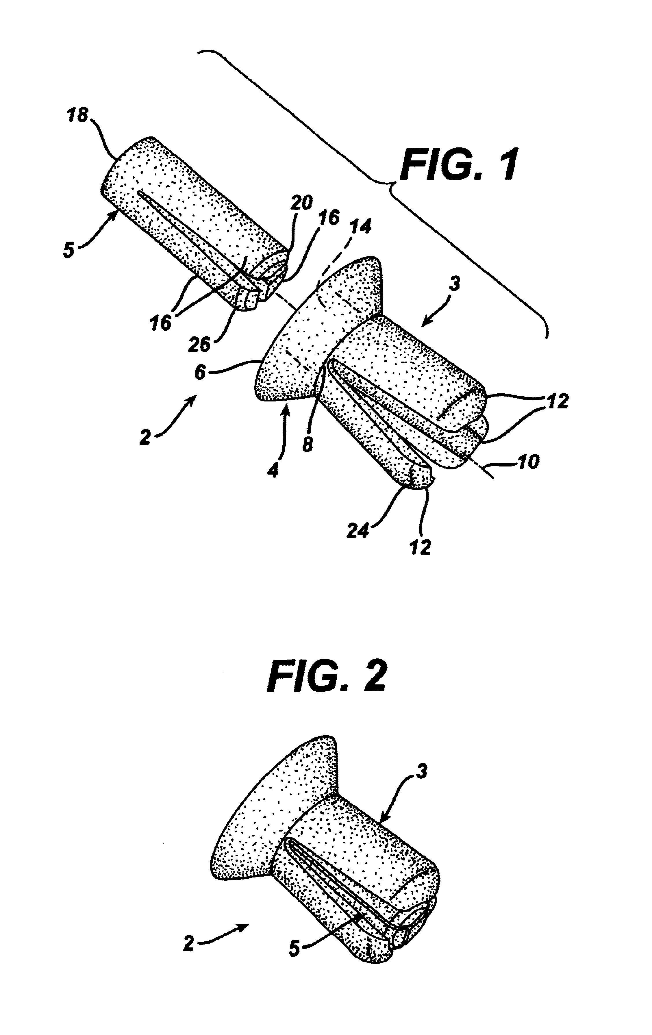
Injection Molding a Rivet and Pin of an 85:15 poly(lactide-co-glycolide) Copolymer 1.5 Kg of the copolymer as formed in Example 1 is added to a nitrogen purged hopper of a 28 ton Engel injection molder equipped with an 18 mm diameter barrel to form a rivet or pin as shown in FIG. 1. Three heating zones of 200, 190, and 185° C. are employed to melt the polymer as it entered the barrel. A nozzle temperature of 185° C. with an injection pressure of 700 psi and a speed of 2 in / s is used to feed the molten material down the barrel. Each injection will produce a single part in a single cavity mold. A temperature of 45° C. is used in the mold to optimize the stress levels in the part. Using this process two parts are formed per minute.

example 3

Step-by-Step Process of Fastener Use in Animal Model or for Human Use

Referring to FIG. 6, after the surgeon has drilled a hole 61 in the bone location where a plate 60 or other device must be fastened, the rivet 4 and pin 5 are loaded into the receiver 68 of the applier 62. The rivet 4 is then inserted into the plate hole 64 and the pin 5 is driven into the rivet 4 by applying a downward force on the plunger 66 of the applier 62. The size of the hole the surgeon drills should be modified based on the type of bone and the cross-sectional diameter of the rivet (with the pin in place). The hole that will be drilled in the bone will necessarily be smaller than the diameter of the rivet with the pin in place. However for bone which is of a soft nature (substantially cancellous bone), the hole diameter may be even smaller to increase the frictional engagement of the rivet and pin fastener with the softer bone. For bone which is harder in nature (substantially cortical bone), the hole diam...


PUM


Abstract

A bioabsorbable rivet and pin fastener is formed as an elongated unit that may be used for anchoring, or for attachment of a fixation plate. The rivet has a head mechanically connected to two or more legs that extend generally distally from the head and may flex outwardly from a central rivet axis. The pin is integral with the rivet and oriented along the central axis by a connection such as a web or a plurality of braces, forming an integral, aligned, one-piece assembly that may, for example, be molded as a single piece. The connection breaks under force as the pin is driven into the rivet, so that the pin contacts internal surfaces of the legs and pushes the legs outward into frictional engagement with the surrounding bone. The one-piece assembly may be formed in a gated mold having a central pin with a relief passage that defines the braces between upper and lower portions of the rivet. The braces so formed at the weld line readily part from the mold, and are easily sheared when the pin is advanced during installation of the rivet.

Description

FIELD OF THE INVENTIONThe field of art to which this invention relates is surgical devices, in particular absorbable orthopaedic fasteners. Specifically, absorbable polymer rivets and pins for use in the fixation of bone, especially hard tissue of the cranium or face, for plastic or reconstructive surgical procedures.BACKGROUND OF THE INVENTIONThere are currently a variety of metallic fasteners available for attaching bone plates to fracture and surgery repair sites; spinal, cranial, and maxillo-facial plates have all been fastened using metal screws. The disadvantage of metal devices is that they are permanent and may need to be removed through a second surgical procedure. If they remain in the body, tissue atrophy and subsequent loosening of the device may occur.Synthetic absorbable biocompatible polymers are well known in the art. Such polymers are typically used to manufacture medical devices, which are implanted in body tissue and absorb over time. Synthetic absorbable biocompa...

Claims


Application Information

Patent Timeline
Patent Type & Authority Patents(United States)
IPC IPC(8): A61B17/68A61B17/58
CPCA61B17/68
Inventor ROGERS, LAUREL L.SAYER, MARIANNOVERAKER, DAVID W.HUXEL, SHAWN T.COOPER, KEVINJAMIOLKOWSKI, DENNIS D.THOMAS, JOSEPH R.
Owner CODMAN & SHURTLEFF INC
Why Eureka
Try Eureka