Wavelength-selectable laser capable of high-speed frequency control

a laser and wavelength technology, applied in the direction of laser details, laser optical resonator construction, optical resonator shape and construction, etc., can solve the problems of requiring a large mechanical configuration in size for wavelength tuning, requiring a complicated and expensive tuning device, and requiring a large mechanical configuration in size, so as to achieve maximum efficiency, minimize the effect of beating signal and maximize the efficiency of polarization mode conversion

Inactive Publication Date: 2005-01-25
FUJITSU LTD
View PDF4 Cites 38 Cited by
  • Summary
  • Abstract
  • Description
  • Claims
  • Application Information

AI Technical Summary

Benefits of technology

According to the above-described wavelength-selectable laser, the first filter is controlled by the frequency of the RF signal so that a laser beam within a specific one of the transmission frequency ranges of the second filter can be transmitted selectively. When the RF signal has a frequency that maximizes the efficiency of polarization mode conversion with respect to the transmission frequency of the second filter, the beat signal is minimized. Accordingly, by controlling the frequency of the RF signal so that the beat signal is minimized or set to be smaller than or equal to a predetermined value, light of the transmission frequency of the second filter can be transmitted with maximum efficiency. That is, by controlling the frequency of the RF signal based on the magnitude of the beat signal of the output light, a laser beam can be controlled to a desired frequency at high speed with accuracy.

Problems solved by technology

When employed in the case of using a large number of FBGs as tunable reflective filters, the above-described method has the disadvantage that two complicated and expensive filters should be tuned simultaneously.
This configuration has the disadvantage of requiring a large mechanical configuration in size for wavelength tuning.
That is, in order to realize the second prior art, the feedback system of the rotation angle of the reflecting grating and a complicated and expensive tuning device are required.
Further, mechanical tuning results in a tuning delay of the order of milliseconds with mechanical stability and reliability being a matter of concern.
However, according to the third prior art, laser oscillation is destabilized by the occurrence of a Doppler frequency shift, and it is extremely difficult to select light of a specific single wavelength using the AOTF.
Other devices such as fiber ring lasers including a tunable filter and an erbium-doped fiber amplifier are slow in gain response and require a relatively long period of time of the order of a few milliseconds in switching wavelengths.
Thus, there is difficulty in downsizing the conventional wavelength-selectable laser, and it is difficult for the conventional wavelength-selectable laser to select light of a specific wavelength or frequency from a broad frequency range in a short period of time with accuracy.

Method used


Image

  • Wavelength-selectable laser capable of high-speed frequency control
  • Wavelength-selectable laser capable of high-speed frequency control
  • Wavelength-selectable laser capable of high-speed frequency control

Examples


first embodiment

[First Embodiment]

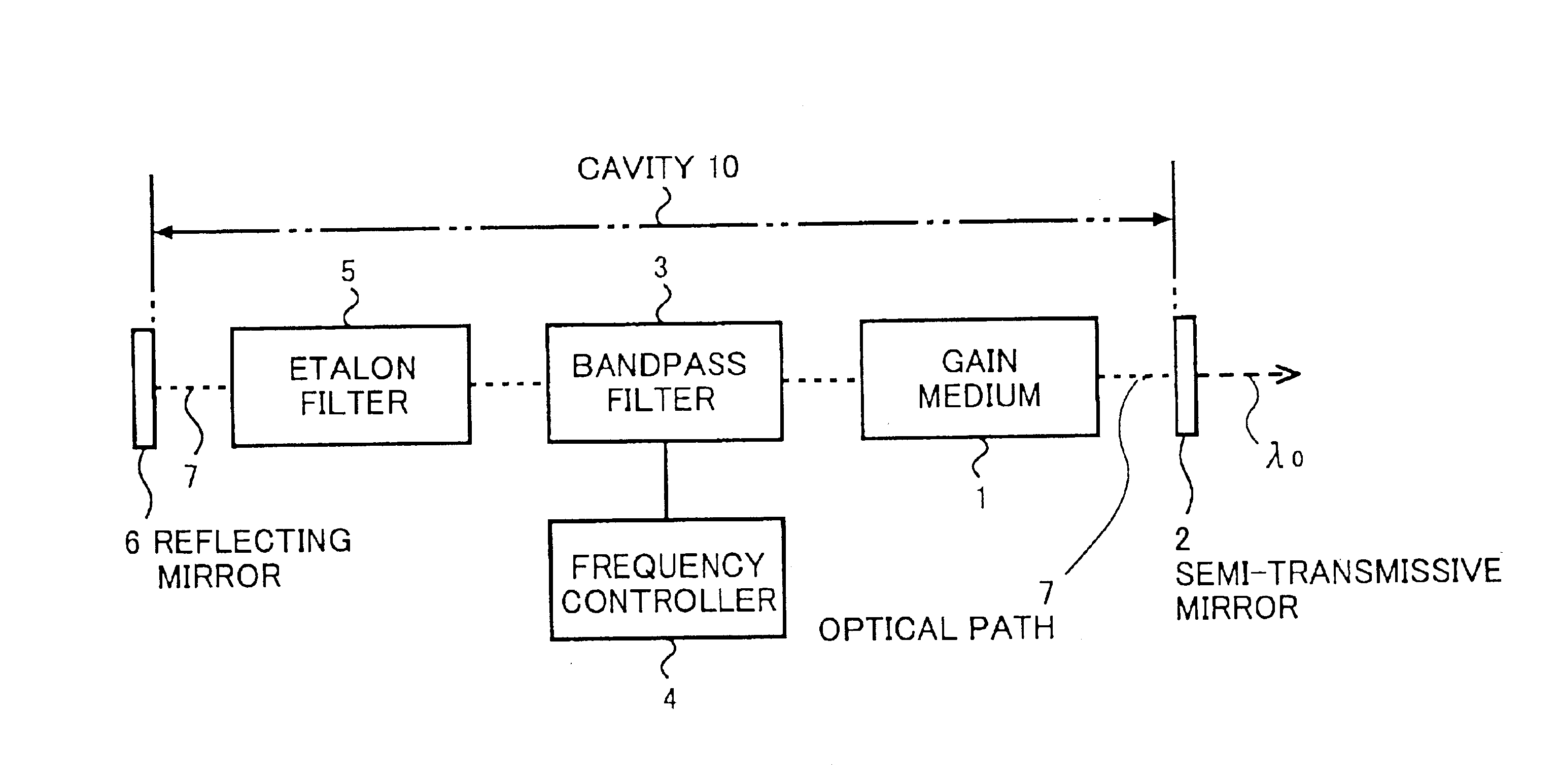
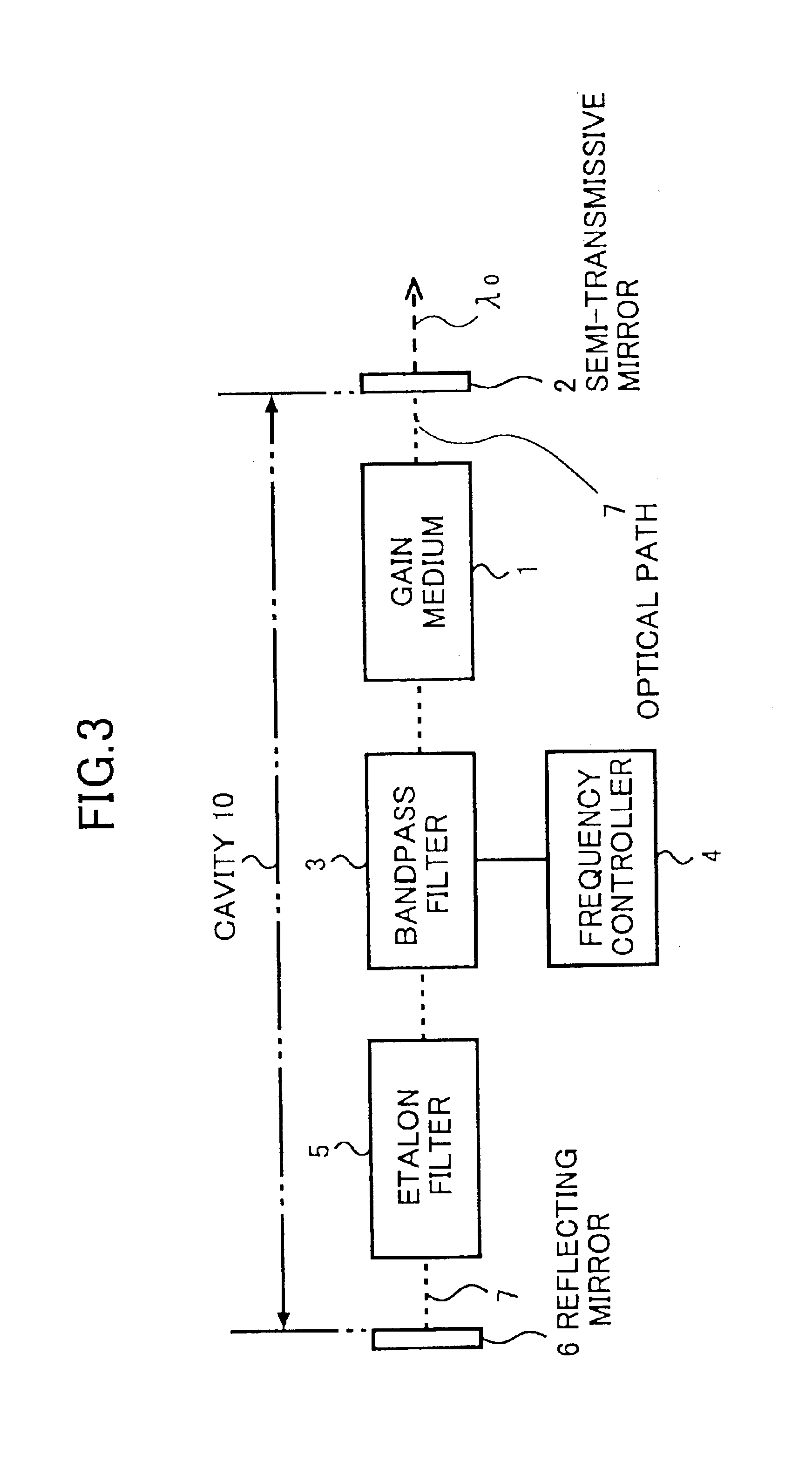
FIG. 3 is a block diagram showing a wavelength-selectable laser according to a first embodiment of the present invention.

According to the wavelength-selectable laser of the first embodiment, a cavity 10 serving as a laser resonator is formed between two reflecting surfaces, i.e., a partially transmissive (semi-transmissive or half) mirror 2 and a reflecting mirror 6. The two reflecting surfaces include at least one semi-transmissive mirror so as to extract a laser beam from the cavity 10. A single-mode optical fiber is connected to the output side of the semi-transmissive mirror 2.

A gain medium 1 for generating optical energy and a solid-state tunable bandpass filter 3 are provided in the cavity 10. The optical energy is generated in a semiconductor optical amplifier (SOA) in the gain medium 1 so as to be distributed typically over a broad frequency range of approximately 100 nm. The bandpass filter 3, which is equivalent to the above-described first bandpass filte...

second embodiment

[Second Embodiment]

An RF signal fs for causing mode conversion (switching) is applied to the AOTF 3. Supplying the RF signal fs and controlling its frequency correspond to the frequency controller 4.

A description will be given of a method as to how the RF signal frequency fs can be controlled to the optimum value.

FIG. 12 is an enlarged view of the AOTF 3. In the AOTF 3, an inter digital transducer (IDT) 214 is formed on a light waveguide 216 formed on the surface of a LiNbO3 substrate by diffusing Ti ions thereon. When the RF signal is applied to the IDT 214, the medium is excited so as to have condensation and rarefaction corresponding to the RF signal, so that an SAW propagates on a field waveguide 218 on the light waveguide 216. As a result, the polarization mode of the propagating light is converted from TE to TM or TM to TE by the interaction between the SAW and the propagating light. This mode conversion occurs with respect only to light of a specific wavelength corresponding ...


PUM


Abstract

A wavelength-selectable laser with a resonance region formed by two reflecting surfaces include a gain medium generating a laser beam, a first filter, and a second filter. The first filter has a first controllable transmission region and transmits a first predetermined wavelength region of the laser beam generated in the gain medium, the first predetermined wavelength region matching the first controllable transmission region. The second filter has a plurality of periodically arranged second transmission regions and transmits a second predetermined wavelength region of the laser beam transmitted by the first filter, the second predetermined wavelength region matching one of the second transmission regions.

Description

CROSS-REFERENCE TO RELATED APPLICATIONThe present application is based on Japanese Laid-Open Patent Applications No. 2002-084254 filed on Mar. 25, 2002 and No. 2002-234462 filed on Aug. 12, 2002, the entire contents of which are hereby incorporated by reference.BACKGROUND OF THE INVENTION1. Field of the InventionThe present invention generally relates to wavelength-selectable lasers, and more particularly to a wavelength-selectable laser whose oscillation frequency can be tuned over a required frequency bandwidth.2. Description of the Related ArtLasers are composed of an optical cavity including a gain medium, and obtain oscillation by increasing the gain. With the recent rapid increase in demand for communication, wavelength division multiplexing (WDM) communication systems that multiplex a plurality of signal beams having different wavelengths to enable mass transmission through a single optical fiber have been developed. Such wavelength division multiplexing optical fiber communi...

Claims


Application Information

Patent Timeline
Patent Type & Authority Patents(United States)
IPC IPC(8): H01S3/106H01S5/14H01S5/00H01S5/062
CPCH01S3/1068H01S5/141H01S3/0632H01S3/082H01S5/142H01S5/101H01S5/1085H01S5/06226
Inventor BOUDA, MARTINMORITO, KENTAKABAYASHI, KAZUMASANAKAZAWA, TADAOHASHIMOTO, NAOKIONAKA, HIROSHIKOTAKI, YUJI
Owner FUJITSU LTD
Why Eureka
Try Eureka