In accordance with another aspect of the invention, an
intelligent agent scheme can be employed wherein various machines, physical entities,
software entities, can be modeled and represented by intelligent
software agents that serve as proxies for the respective machines or entities. These agents can be designed to interact with one another and facilitate converging on various modifications and control of the machines of entities in connection with efficiently optimizing an overall business concern. Lower level agents may collaborate and negotiate to achieve lower level process objectives in an optimal manner and integrate this information to higher level agents. Agents, may compete with each other for
limited resources and become antagonistic in order to realize critical objectives in a save, reliable, and optimum manner. Moreover, the agents may comprise a highly distributed system controlling the operation of a complex dynamic process. There may not exist a central point or control or coordination of the system. Rather information is distributed among the various agents. Groups of agents may form clusters to promote meeting operational objectives such as
local agent goals as well as to promote
collaboration in meeting higher-level system goals and objectives. During negotiation for services and functions, local agents may also provide “cost” information to other agents indicating efficiency, energy utilization, or robustness for example. Agents may assign functions and control
modes to particular agents based on a comparison and optimization of the specified cost function or operational objective or objectives to be optimized.
Moreover, it is to be appreciated the subject invention can be employed in connection with initial specification,
layout and design of an industrial
automation system (e.g., process, factory) such that high-level
business objectives (e.g., expected revenue, overhead,
throughput, growth) are considered in connection with predicted
machine characteristics (e.g., life cycle cost, maintenance,
downtime, health, efficiency, operating costs) so as to converge on specifications,
layout, and design of the industrial
automation system so that a mapping to the high-level
business objectives is more closely met as compared to conventional schemes where such
layout and design is performed in more or less an ad hoc, manual and arbitrary manner. Integrating information regarding opportunities for real-time
prognostics and optimizing control can influence the initial design and configuration of the system to provide additional
degrees of freedom and enhance the capability for subsequent
prognostics and optimizing and compensating control.
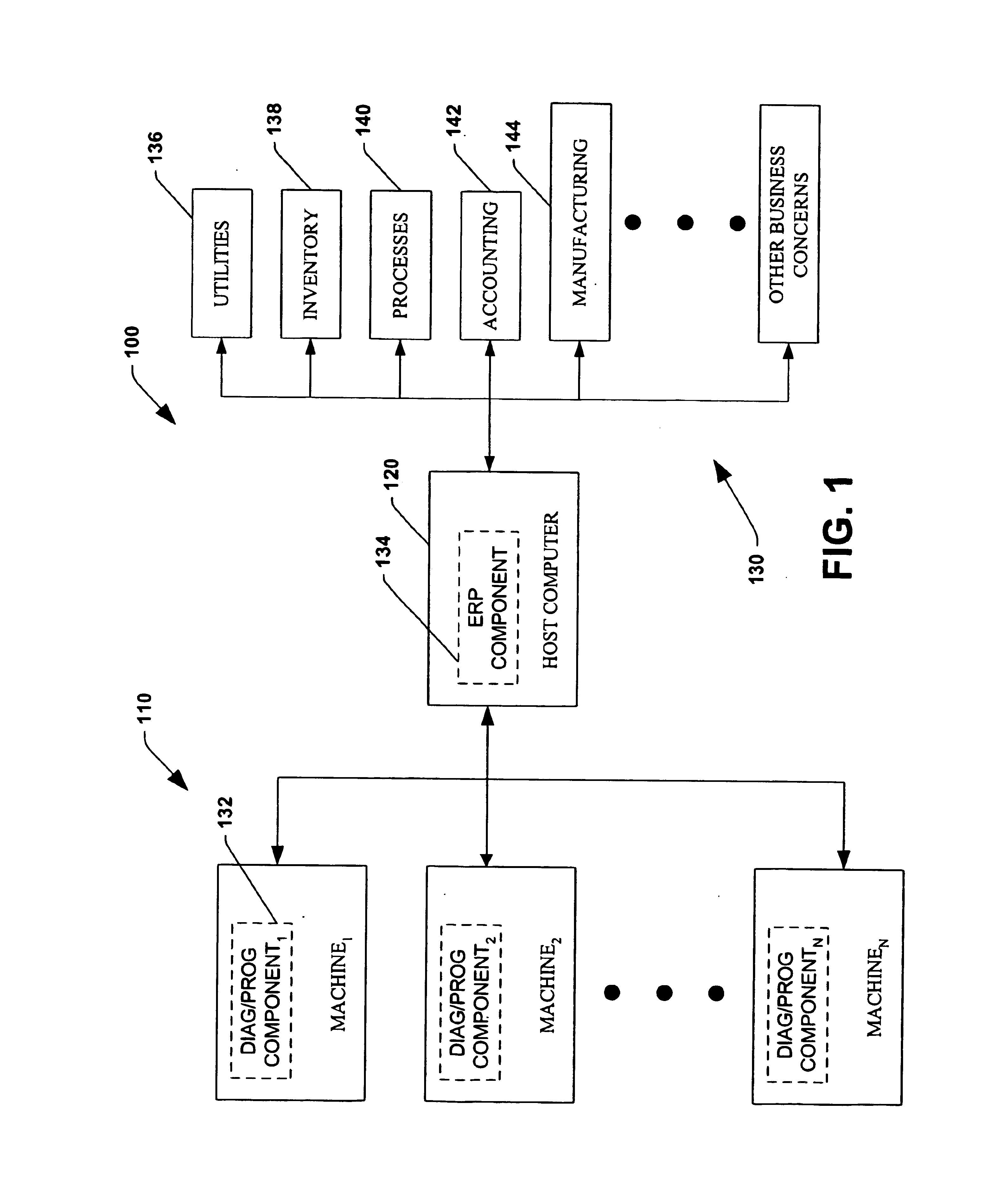
In addition, the system may obtain such information from a host computer and / or other information systems, scheduling systems, inventory systems,
order entry systems, decision support systems, maintenance scheduling systems, accounting systems or control systems among others within a larger process via a network or
wireless communications. Moreover, this information may be obtained via a
wide area network or global communications network, such as
the Internet. In this regard, the optimization of one or more performance characteristics may be optimized on a global, enterprise-wide or process-wide basis, where, for example, a single pump system may be operated at a less than optimal efficiency in order to facilitate the operation of a larger (e.g., multi-pump) process or system more efficiently. A specific pump may provide low
throughput and run inefficiently to meet minimum product requirements due to the fact that another system in the enterprise can provide additional
processing at a much more cost-effective rate and will be run at maximum
throughput.
Thus, for example,
signal processing may be performed in order to ascertain wear, failure, remaining useful lifetime, or other deleterious effects on system performance, whereby the control of the system may be modified in order to prevent further degradation, extend the remaining service life of one or more system components, or to prevent unnecessary stress to other system components. In this regard, the diagnostic component may process signals related to flow, pressure, current,
noise, vibration, and temperature associated with the motorized system. The altered system control may extend the life of the machinery to maximize throughput while insuring there is not failure for a specified period of time and not longer. Having the machinery live longer than the minimum necessary will require operating the machinery at an even lower level of efficiency. For example our objective may be to maximize throughput or efficiency while just meeting the minimum required lifetime and not longer.

