System and method for effecting high-power beam control with outgoing wavefront correction utilizing holographic sampling at primary mirror, phase conjugation, and adaptive optics in low power beam path

a technology of adaptive optics and beam path, applied in the field of optics, can solve the problems of reducing durability and/or increasing manufacturing cost, limiting the performance of conventional adaptive optics systems using deformable mirrors, and delicate optical devices in the path of high-power energy beams

Inactive Publication Date: 2005-02-01
RAYTHEON CO
View PDF17 Cites 45 Cited by
  • Summary
  • Abstract
  • Description
  • Claims
  • Application Information

AI Technical Summary

Benefits of technology

A master oscillator provides a low power reference beam, which illuminates the optical phased array and provides a beam-path wavefront error corrected signal in response thereto. After sampling the refractive distortion in the aperture sharing element (ASE) the beam-path wavefront error corrected signal illuminates the back of the ASE and back reflects off the front surface of the element. This signal, in turn, is conjugated by the first phase conjugate mirror and transmitted through the ASE to the second phase conjugate mirror. The second phase conjugate mirror conjugates the transmitted signal thus canceling the effect of the first phase conjugation process. This signal is then amplified and front reflected off the front surface of the ASE to provide the output beam to the beam director telescope, where it is directed to the target. As the front and back reflections off the front surface of the aperture sharing element are phase conjugates of one another, the reflective distortion due to this element, which is not shared by the target track sensor optical path, is removed. Refractive distortions, which are not shared by the target track sensor optical path such as in the aperture sharing element, laser amplifiers, and other optical elements are also removed in this embodiment via the wavefront reversal properties of the first and second phase conjugate mirrors. The residual optical distortions in the laser beam path from the master oscillator output to the target are, therefore, essentially the same as the optical distortions from the target to the target track sensor; and the correction signal applied to the optical phased array also corrects the beam path for the target track sensor.

Problems solved by technology

Unfortunately, the use of delicate optical devices in the path of a high-power energy beam is problematic.
Therefore, coatings may need to be applied at lower than optimal temperature using more complex coating processes, thereby reducing durability and / or increasing manufacturing cost.
In addition, conventional adaptive optics systems using deformable mirrors are limited in performance.
There is also a limitation with respect to the number actuators that can be used.
The stroke of the conventional deformable mirror is limited.
Further, a conventional continuous face sheet deformable mirror cannot correct for a pathology in the spatial phase pattern, such as a branch point or an abrupt phase discontinuity.
However, this scheme is practical only with a coherently-combined array of single-mode fiber amplifiers, as each fiber channel is correctable in piston only, not high order.
Also, this scheme is not applicable to multi-mode laser media such as large core fiber amplifiers or bulk media lasers as contemplated for weapon class HEL devices and may not be scaleable to high power levels due to random, high frequency phase noise caused by pump-induced temperature fluctuations within the fibers.
This approach, however, places the LCLV in the high power beam path and is therefore limited by the damage susceptibility of the liquid crystal material.
Such a deployable segmented mirror will have significant figure and static and dynamic piston phase errors due to the low stiffness pedals and physical arrangement of the deployment mechanism.
Unfortunately, this approach is limited by the performance of conventional deformable mirror technology, particularly the limited stroke and inability to accommodate discontinuities in phase created by the pedal joints.
Unfortunately, while effective when integrated local- and target-loop adaptive optics are used, this architecture does not adequately address the needs of current and proposed space based applications.

Method used


Image

  • System and method for effecting high-power beam control with outgoing wavefront correction utilizing holographic sampling at primary mirror, phase conjugation, and adaptive optics in low power beam path
  • System and method for effecting high-power beam control with outgoing wavefront correction utilizing holographic sampling at primary mirror, phase conjugation, and adaptive optics in low power beam path
  • System and method for effecting high-power beam control with outgoing wavefront correction utilizing holographic sampling at primary mirror, phase conjugation, and adaptive optics in low power beam path

Examples


Embodiment Construction

Illustrative embodiments and exemplary applications will now be described with reference to the accompanying drawings to disclose the advantageous teachings of the present invention.

While the present invention is described herein with reference to illustrative embodiments for particular applications, it should be understood that the invention is not limited thereto. Those having ordinary skill in the art and access to the teachings provided herein will recognize additional modifications, applications, and embodiments within the scope thereof and additional fields in which the present invention would be of significant utility.

The present teachings will be made clear with an initial review of the following.

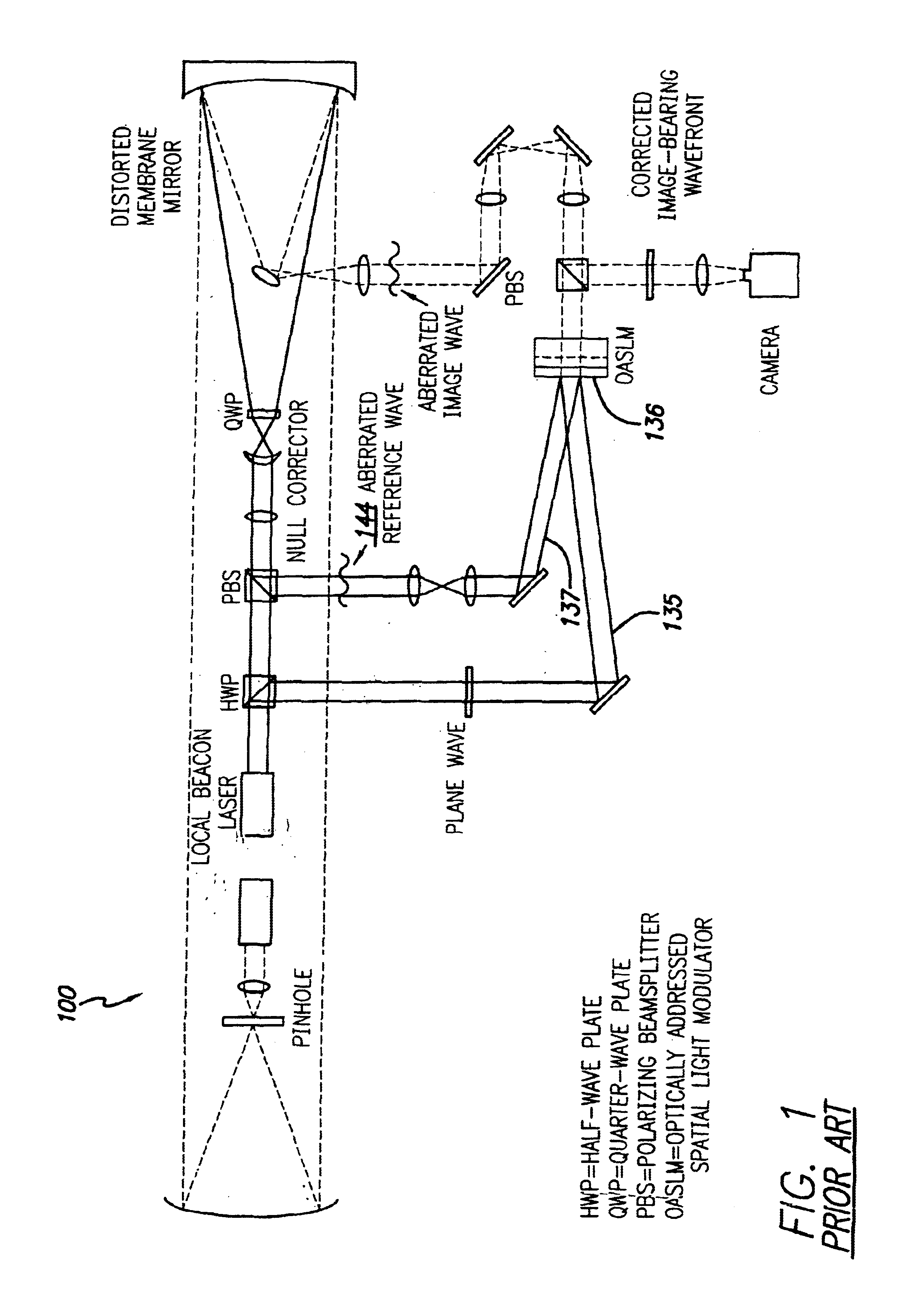
Compensated Imaging by Real-Time Holography with Optically-Addressed Liquid-Crystal Spatial Light Modulators

Several groups have demonstrated aberration correction for large primary mirrors and atmospheric turbulence using real-time holographic techniques that are based on optically-...


PUM


Abstract

A beam control system and method. In an illustrative embodiment, the inventive system (500) provides a first beam of electromagnetic energy (503); samples the first beam (503) and provides a second beam (505) in response thereto; detects aberrations in the second beam (505); and corrects aberrations in the first beam (503) in response to the detected aberrations. In a specific implementation, the invention (500) includes a beam director telescope (510) having a primary mirror (516) on which a holographic optical element (518) is disposed. The holographic optical element (518) samples the output high-power beam and provides a sampled beam to a wavefront sensor (520). The wavefront sensor (520) provides signals to an adaptive optics processor (580). The adaptive optics processor (580) analyzes the sampled wavefront, detects aberrations therein and provides a correction signal to an optical phased array (550).

Description

BACKGROUND OF THE INVENTION1. Field of the InventionThe present invention relates to optics. More specifically, the present invention relates to systems and methods for directing and correcting high-power beams of electromagnetic energy.2. Description of the Related ArtDirected energy weapons and specifically high-energy laser (HEL) weapons are being considered for variety of military applications with respect to a variety of platforms, e.g., spaceborne, airborne and land based systems to name a few. These weapons generally involve the use of the laser or other source of a high-energy beam to track and destroy a target. To achieve mission objectives, directed energy weapons must be accurately steered and optimally focused. Steering involves line-of-sight control while focusing, with respect to HEL weapons, involves wavefront error correction. Currently, wavefront error correction is typically achieved using adaptive optics. The current state of the art in laser beam control adaptive...

Claims


Application Information

Patent Timeline
Patent Type & Authority Patents(United States)
IPC IPC(8): G02B26/06G02B27/00G02B26/00
CPCG02B27/0037G02B26/06
Inventor BYREN, ROBERT W.TRAFTON, ALVIN F.
Owner RAYTHEON CO
Why Eureka
Try Eureka