

Backplane utopia bus
- Summary
- Abstract
- Description
- Claims
- Application Information
AI Technical Summary
Benefits of technology
Problems solved by technology
Method used
Image

Examples
Embodiment Construction
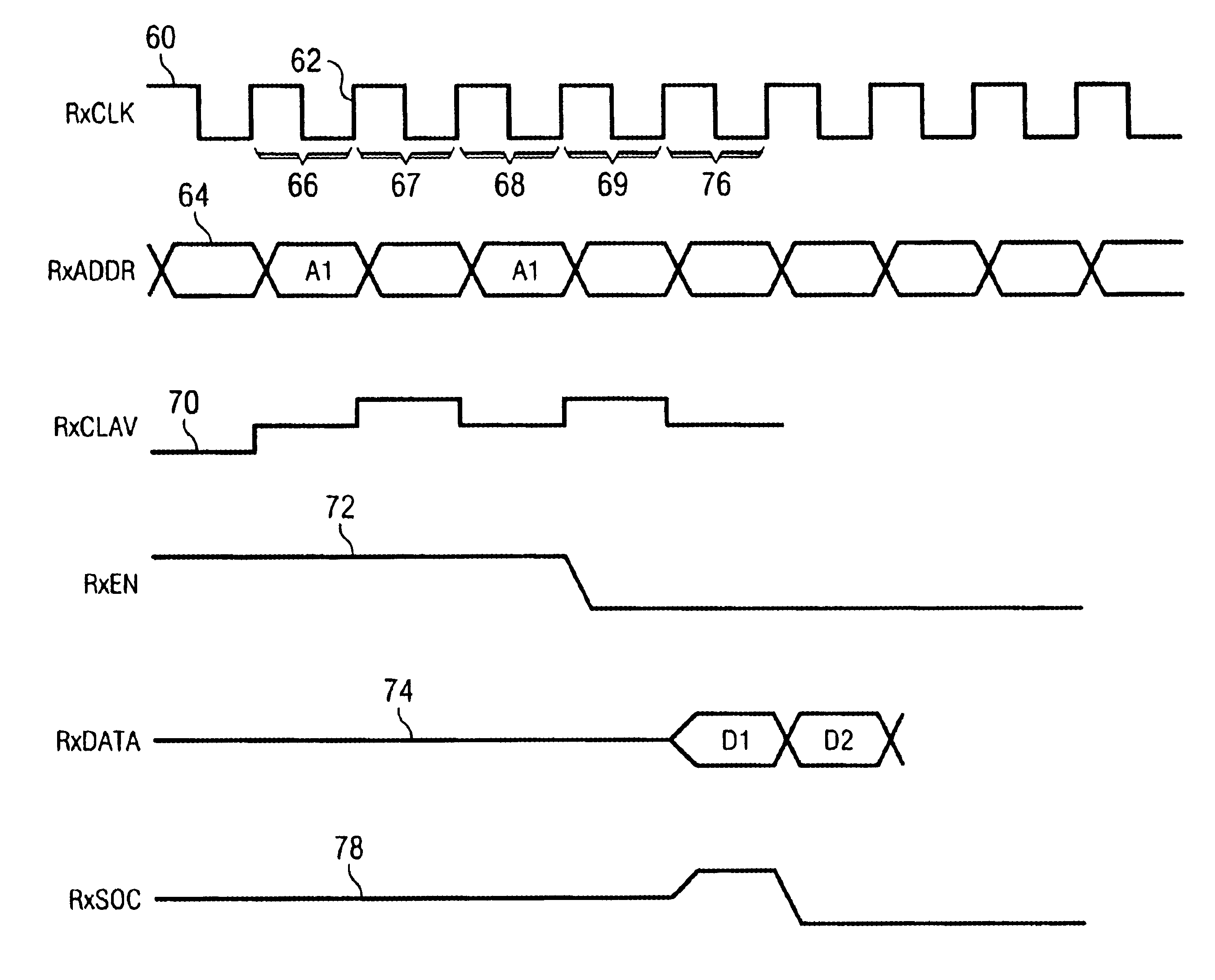
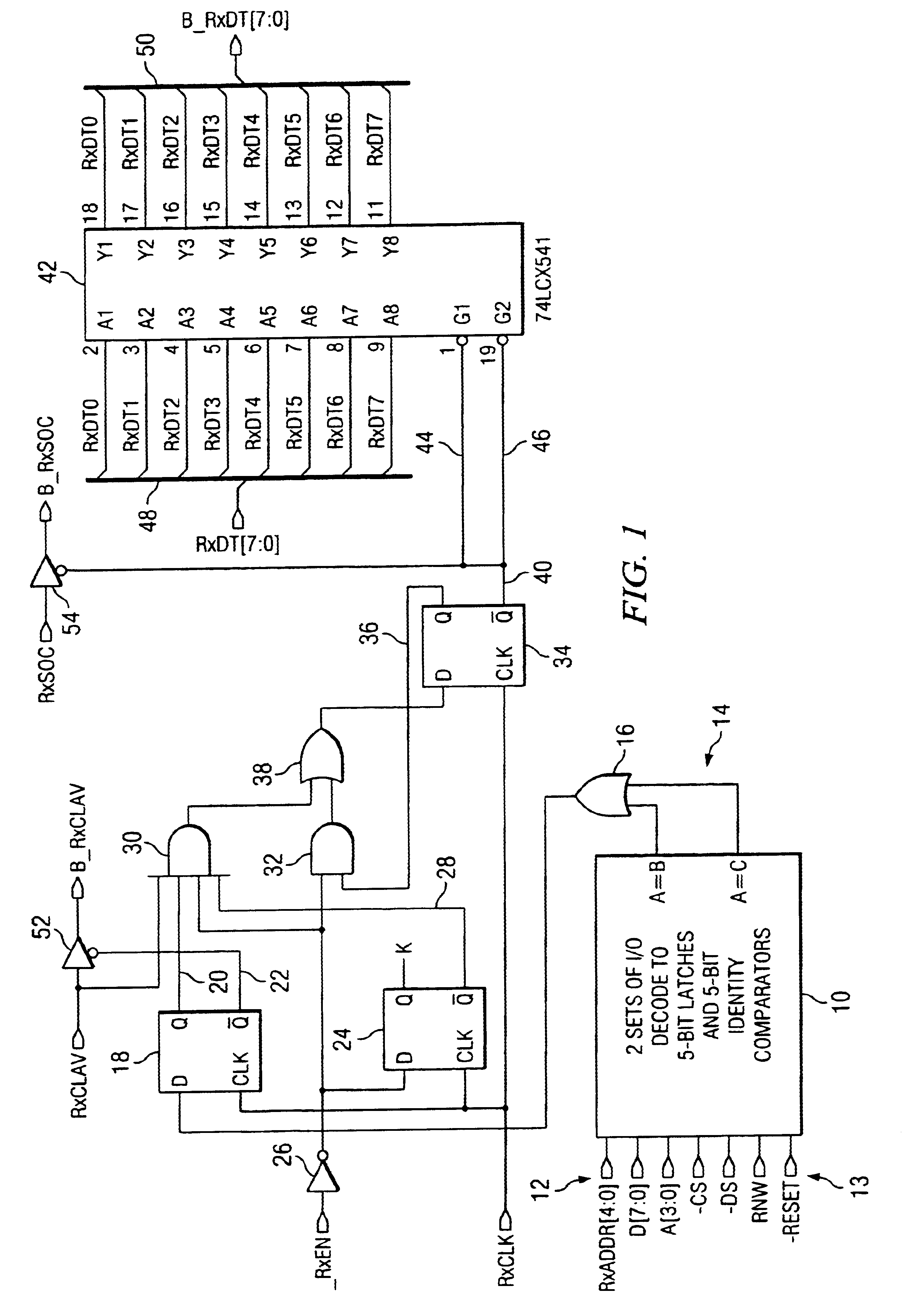
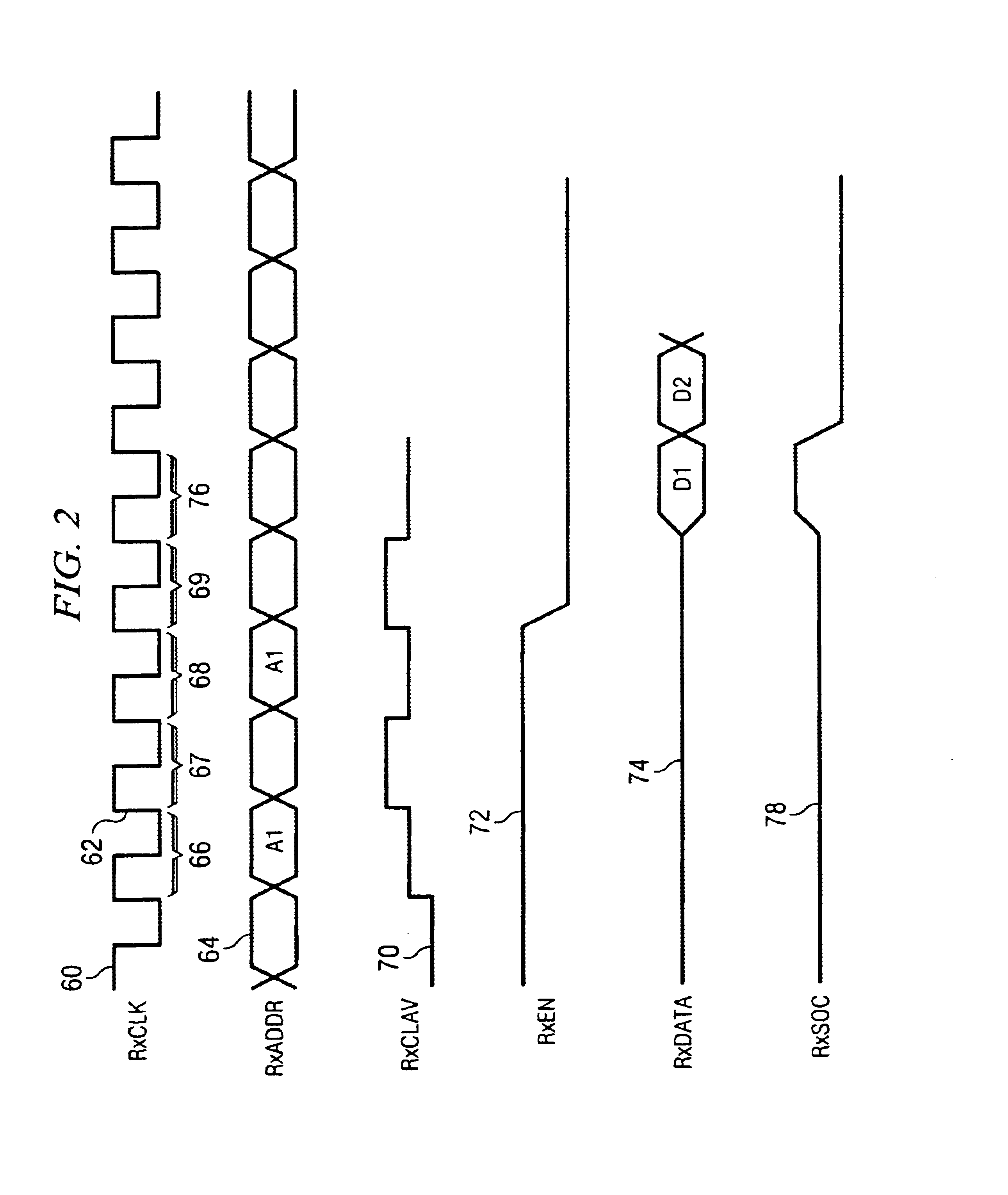
With reference to FIG. 1, there is provided a schematic diagram of an embodiment of the present invention using standard logic element representations. An address detection logic unit 10 contains 5-bit identity comparison logic devices, and has inputs 12 for receiving the receive address signals from the ATM layer which controls the overall system. Within unit 10 is one or more register(s) which store the UTOPIA 2 address(es) of selected peripheral device(s) residing on the same printed circuit board as the circuitry of the present invention. These registers are written by the central system controller in a very standard way using normal address (A), data (D), chip select (CS), data strobe (DS), and read / write direction (RNW) control lines 13. A reset input is also provided to set the registers to a known state. In the preferred embodiment, these registers are reset to the UTOPIA 2 ‘null address’ number (all ‘ones’). This value cannot be a valid PHY address, so logic in block 10 als...
PUM
 Abstract
Description
Claims
Application Information