MR imaging using nested pulse sequence involving IR pulse

Inactive Publication Date: 2005-02-01
KK TOSHIBA
View PDF2 Cites 41 Cited by
  • Summary
  • Abstract
  • Description
  • Claims
  • Application Information

AI Technical Summary

Benefits of technology

Accordingly, an object of the present invention is to provide a method of acquiring an MR signal with a high signal-to-noise ratio, a magnetic resonance imaging method, and a magnetic resonance imaging system, in which the level of an MR signal induced by a pool of nuclei such as free water can be raised and a “positive” MTC effect can be yielded.
When the “reverse” MT effect is used to perform magnetic resonance imaging or ST-based spectroscopy, since the level of an MR signal gets higher, the resolution of a contrast image can be upgraded. Moreover, the analytic capability of spectroscopy can be improved.

Problems solved by technology

As a result, the signal-to-noise ratio of the signal is low.
This leads to a decrease in signal strength.
Moreover, since such imaging techniques do not take account of the MT effect and an interpulse time between applied inversion pulses is often not uniform, irregular sensitivity occurs between slices due to the MT effect.
This presumably deteriorates the contrast between, for example, white matter and gray matter.
However, in imaging employing an IR-(inversion recovery) system pulse sequence, imaging techniques making use of the MT effect have not yet been developed.

Method used


Image

  • MR imaging using nested pulse sequence involving IR pulse
  • MR imaging using nested pulse sequence involving IR pulse
  • MR imaging using nested pulse sequence involving IR pulse

Examples


first embodiment

the present invention will be described with reference to FIGS. 1 to 7.

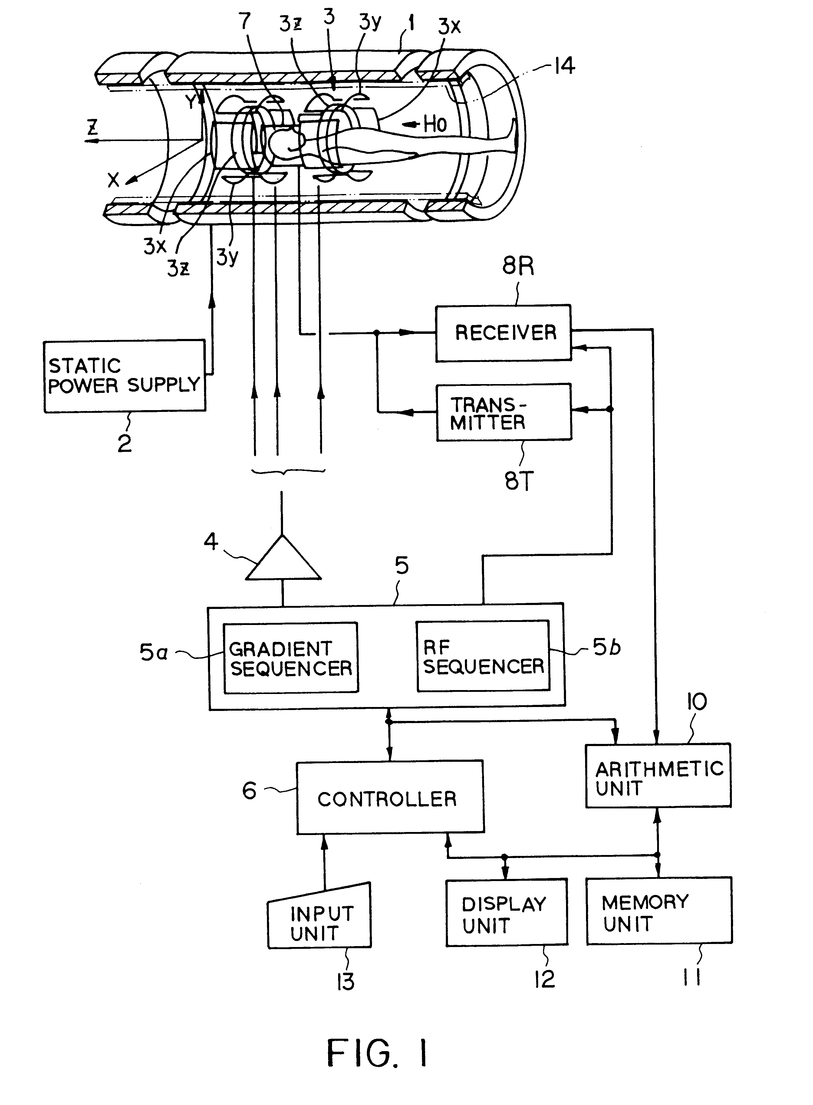
FIG. 1 shows an outline configuration of a magnetic resonance imaging system in accordance with this embodiment. This magnetic resonance imaging system comprises a magnet unit for generating a static magnetic field, a magnetic field gradient unit for appending position information to a static magnetic field, a transmitting and receiving unit for receiving an MR signal, and a control and arithmetic unit responsible for system control and image reconstruction.

The magnet unit comprises a superconducting magnet 1 and a static power supply 2 for supplying a current to the magnet 1, and generates a static magnetic field H0 in a Z-axis direction in a cylindrical aperture into which a patient P is inserted. The magnet unit is provided with shim coils 14 for primary shimming. By regulating a current to be supplied to the shim coils 14, shimming is achieved.

The magnetic field gradient unit includes three pairs of gradient ...

second embodiment

the present invention will be described with reference to FIGS. 11 to 31.

The schematic configuration of a magnetic resonance imaging system in accordance with this embodiment is a magnetic resonance imaging system comprising the same components as those in the first embodiment (refer to FIG. 1). The gradient sequencer 5a has a computer and receives a signal commanding an acquisition pulse sequence employed in fast FLAIR or the like from a controller 6 (having a computer) for controlling the whole system. The controller 6 executes scan planning as described in FIG. 26 through interaction via the input unit 13.

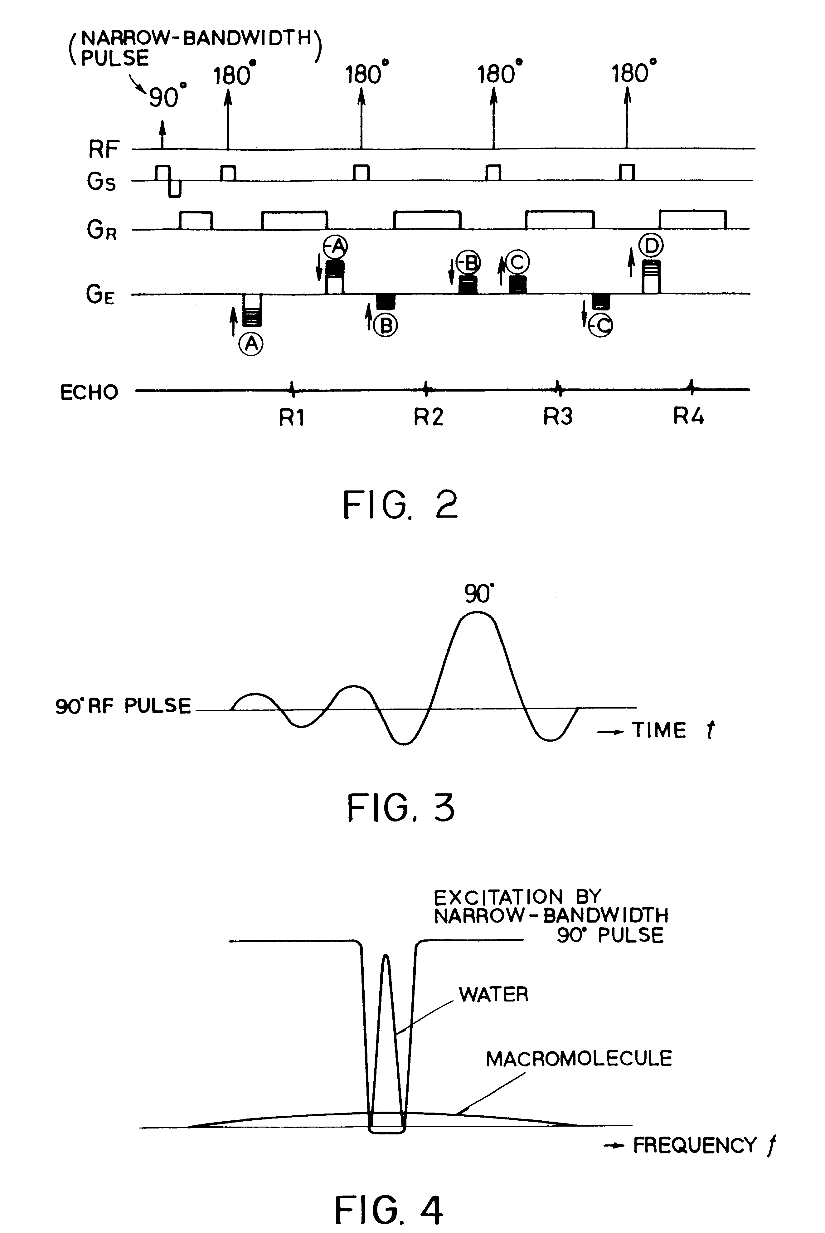
Several features concerning imaging adopted by this embodiment will be described.(1) Usable pulse sequence

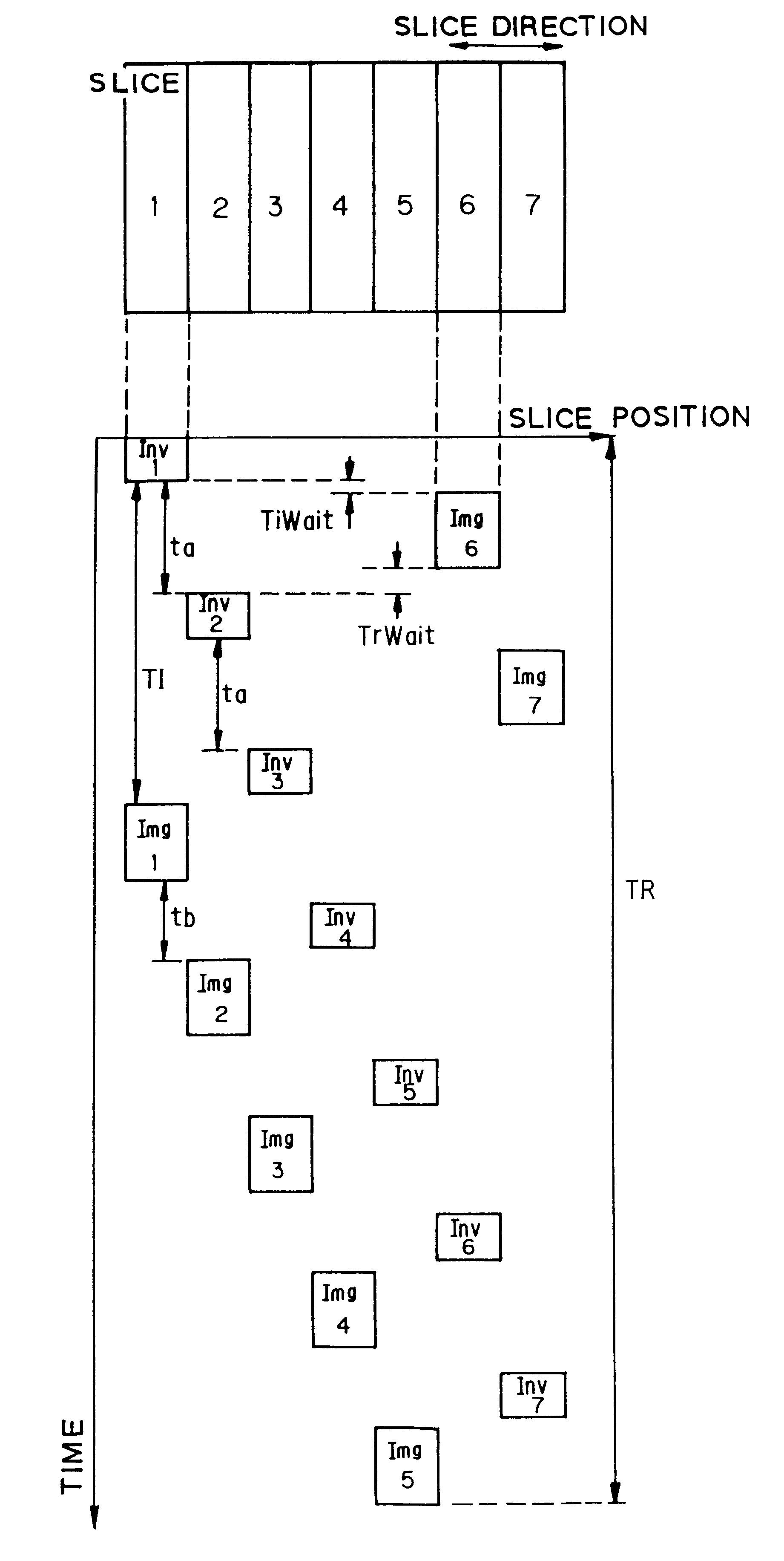
A pulse sequence usable for the magnetic resonance imaging system of the second embodiment is an IR (inversion-recovery) pulse sequence including an inversion pulse.

To be more specific, a pulse sequence that is a combination of an inversion pulse (frequently, referred to as ...


PUM


Abstract

In addition to the known MT (magnetization transfer) effect, an RMT (reverse MT) is newly found, which increases a detected MR signal strength. Both the MT and RMT effects can be explained with mutual interaction, such as phenomena of chemical exchange and / or cross relaxation, acted between a pool of water proton spins and another pool of macromolecule proton spins, for example, within an object. In order to enhance the MT or RMT effect, the frequency bandwidths of RF pulses, such as a 90° RF exciting pulse in a SE or FSE method, an inversion pulse in a FLAIR or fast FLAIR method, and others, are controlled. To enhance the MT effect, the bandwidth is controlled into a wider value (approx. more than 1250 Hz) than the normally (conventionally) used bandwidth, while to obtain the RMT effect, the bandwidth is controlled into a narrower value (approx. less than 1000 Hz) than the normally used bandwidth. Actively controlling the MT or RMT effect permits changed image contrast in MR imaging.

Description

BACKGROUND OF THE INVENTION1. Field of the InventionThe present invention relates to a magnetic resonance imaging based on magnetic resonance phenomena exhibited by spins of nuclei. More particularly, this invention is concerned with medical-purpose magnetic resonance imaging method and magnetic resonance imaging system for executing imaging that uses mutual interaction between different kinds of pools of nuclear spins.2. Description of the Related ArtCurrently, a technique in which a “magnetization transfer” (MT) effect (or “magnetization transfer contrast” (MTC) effect) is utilized to produce a contrast image whose contrast resolution varies depending on whether a living body exerts the MT effect is known as one of various medical resonance imaging techniques. A practical example of this imaging technique has been disclosed in U.S. Pat. No. 5,050,609 (“Magnetization Transfer Contrast and Proton Relaxation and Use Thereof in Magnetic Resonance Imaging” filed by Robert S. Balanban e...

Claims


Application Information

Patent Timeline
IPC IPC(8): G01R33/54
CPCG01R33/54
Inventor MIYAZAKI, MITSUEKASSAI, YOSHIMORI
Owner KK TOSHIBA
Why Eureka
Try Eureka