Robotic method of transferring workpieces to and from workstations

a workpiece and robot technology, applied in the direction of lapping machines, charge manipulation, furnaces, etc., can solve the problems of consuming a significant amount of clean room space, affecting the polishing process, and affecting the polishing effect of the optical scan vision system, so as to enhance the polishing process and increase the effect of optical scanning vision system

Inactive Publication Date: 2005-02-08
NOVELLUS SYSTEMS
View PDF44 Cites 20 Cited by
  • Summary
  • Abstract
  • Description
  • Claims
  • Application Information

AI Technical Summary

Benefits of technology

Another feature of the present invention is a wafer mapping system which determines which slots within a wafer cassette is occupied by wafers. The mapping system also determines whether wafers are properly aligned within the slots and whether more than one wafer is within a particular slot. The mapping system preferably comprises an optical scanning device, such as a video camera, mounted in a mounting bracket attached to a top portion of the robot and a system processor configured to interpret and process the signals from the scanning device. When a cassette is placed on the polishing and cleaning machine, the robot end-effector retrieves the scanning device (camera) from the mounting bracket and traverses up and down in front of the cassette, allowing the optical scanner to view the contents of the cassette. Additionally, a back lighting source behind the cassette may be utilized to increase the effectiveness of the optical scan vision system.
The CMP station is preferably configured to receive and polish five wafers at a time. After the wafers are loaded by the robot onto an index table, a multi-head transport apparatus lowers five wafer carrier heads into proximity with the index table and picks up the wafers. The transport apparatus then moves laterally until it is positioned above a polishing surface. The transport apparatus is then lowered such that the wafers are pressed against the polishing surface. To enhance the polishing process, a polishing slurry is preferably provided, and the individual carriers are rotated on and oscillated radially across the polishing surface. After polishing, the wafers are returned to unload cups in the index table. A flipper apparatus then transfers the wafer from the unload cups to the cleaning station of the machine.

Problems solved by technology

If these particles dry on the wafer prior to cleaning, the microelectronic structures on the wafer may be corrupted.
This conventional practice of utilizing separate machines for wafer polishing and for wafer cleaning and drying has serious drawbacks.
First, wafer manufacturers must have personnel, equipment and facilities on hand to transport wafers in a wet environment from a CMP machine to a cleaning and drying machine.
Secondly, having separate machines for polishing wafers and for cleaning wafers consumes a significant amount of clean room space which, as one skilled in the art will appreciate, is very expensive.

Method used


Image

  • Robotic method of transferring workpieces to and from workstations
  • Robotic method of transferring workpieces to and from workstations
  • Robotic method of transferring workpieces to and from workstations

Examples


Embodiment Construction

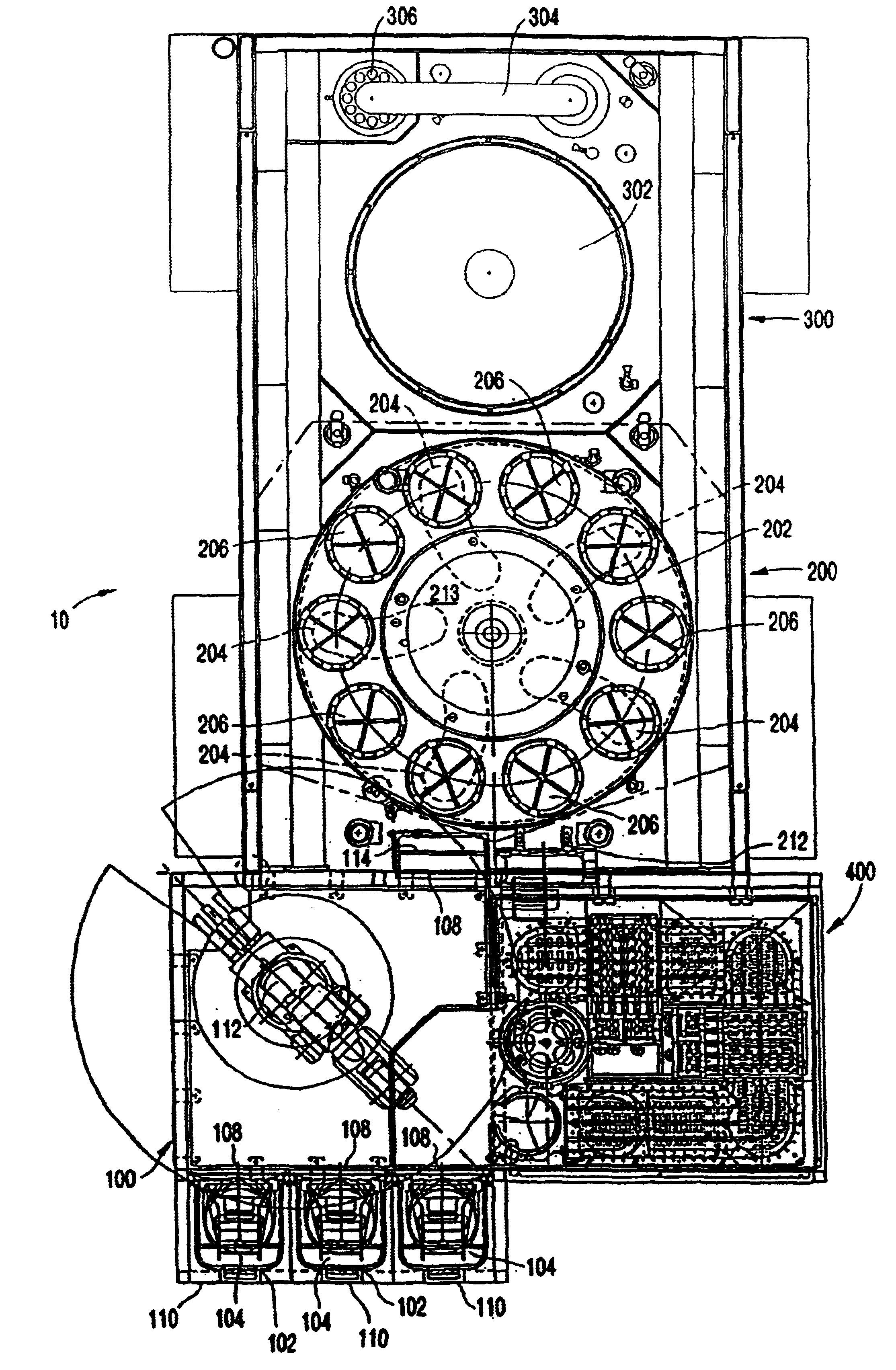
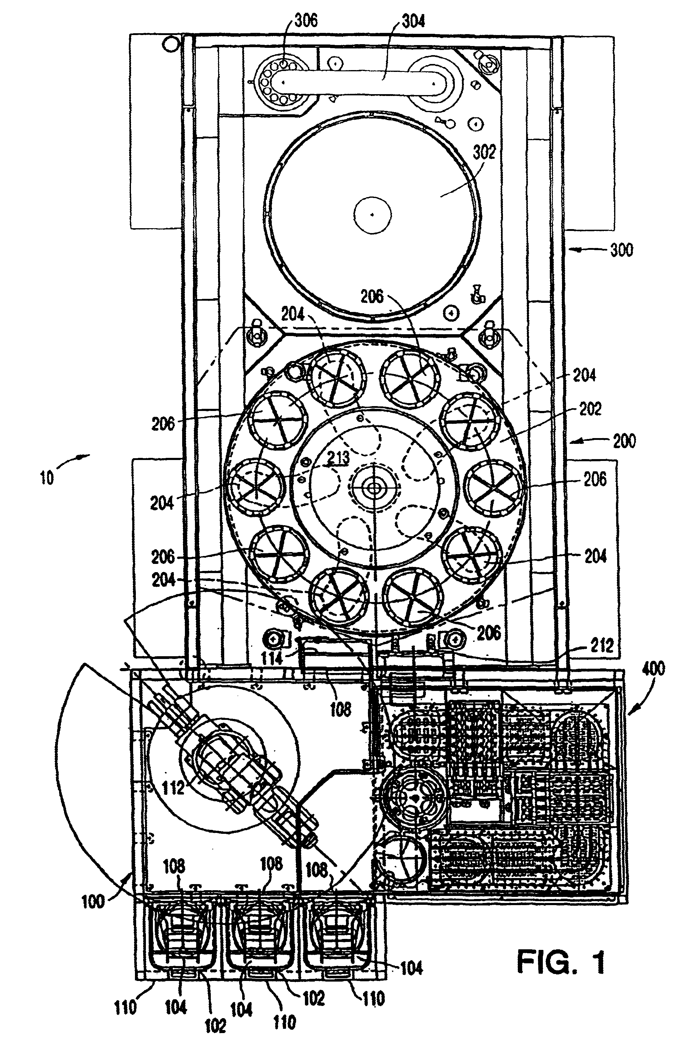
An integrated wafer CMP polishing and cleaning machine 10 according to the present invention is illustrated in FIG. 1. Machine 10 comprises wafer load / unload station 100, wafer index station 200, wafer CMP station 300, and wafer cleaning station 400. Each of the foregoing stations are structurally and functionally described in greater detail below.

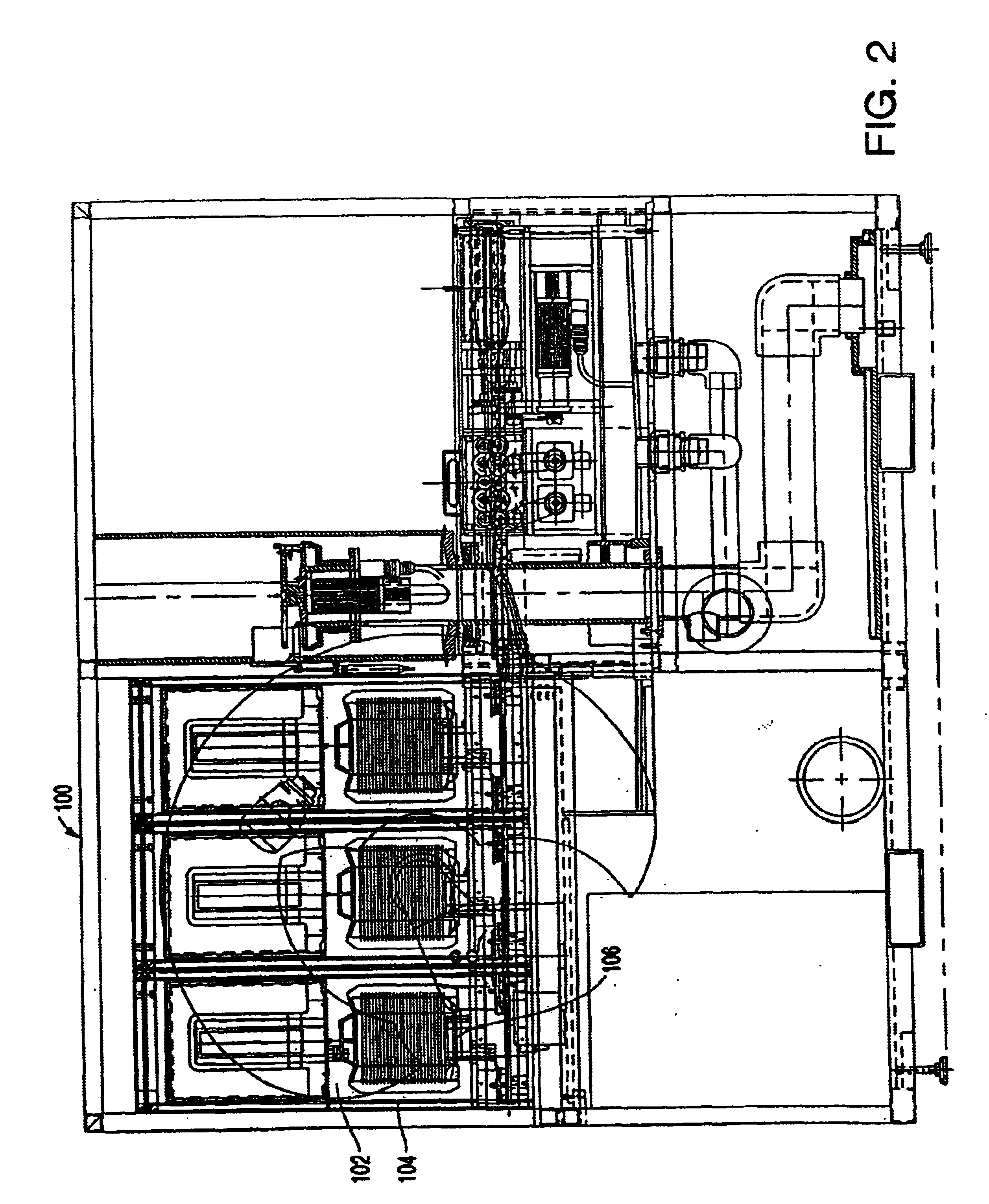
With continued reference to FIG. 1 and additional reference to FIGS. 2 and 3, wafer load / unload station 100 is configured to accommodate a plurality of wafer cassettes to permit substantially continuous operation of machine 10. Preferably, load / unload station 100 includes three wafer cassette platforms 102, each configured to hold at least one wafer cassette 104 full of wafers to be polished and cleaned. In this regard, although the present invention is described in the context of exemplary workpieces such as semiconductor wafers, virtually any substantially flat, substantially circular workpiece may be employed in the context of the prese...


PUM

PropertyMeasurementUnit
angleaaaaaaaaaa
angleaaaaaaaaaa
movementaaaaaaaaaa

Abstract

An integral machine for polishing, cleaning, rinsing and drying workpieces such as semiconductor wafers. A load/unload station has a plurality of platforms for receiving cassettes of wafers to be processed. A dry end-effector of a robot retrieves wafers from the cassettes and transfers them to an index table. A transfer apparatus having wafer carrier elements picks up wafers from the index table, moves the wafers to a polishing table for polishing, and returns the wafers to the index table for further processing. A flipper moves the polished wafers to a cleaning station. The cleaning station includes scrub stations, a rinsing station and a spin dryer station, and a connective system of water tracks. A wet end-effector of the robot transfers rinsed wafers to the spin dryer station. The dry end-effector of the robot moves dried wafers from the spin dryer station back to the cassette of origination.

Description

FIELD OF THE INVENTIONThe present invention relates, generally, to a self-contained machine for polishing, cleaning, rinsing, and spin-drying semiconductor wafer workpieces and, more particularly, to an improved system for receiving a cassette of wafers; CMP polishing, cleaning, rinsing and drying the wafers; and returning the polished and cleaned wafers to the same cassette and to the same slot from which they were taken.BACKGROUND OF THE INVENTIONMachines for polishing and machines for cleaning wafers and disks in the electronics industry are generally well known. For example, semiconductor wafers, magnetic disks, and other workpieces often come in the form of flat, substantially planar, circular disks. In the manufacture of integrated circuits, semiconductor wafer disks are sliced from a silicon ingot and prepared for further processing. After each wafer is sliced from the ingot, it must be thoroughly polished and then cleaned, rinsed, and dried to remove debris from the surface ...

Claims


Application Information

Patent Timeline
Patent Type & Authority Patents(United States)
IPC IPC(8): B24B37/04B24B41/00H01L21/02H01L21/306B65G49/07H01L21/304H01L21/677
CPCB24B37/04H01L21/02052B24B41/005H01L21/304
Inventor GONZALEZ-MARTIN, JOSE R.KARLSRUD, CHRIS
Owner NOVELLUS SYSTEMS
Why Eureka
Try Eureka