Organic electroluminescent device based on pyrene derivatives

Inactive Publication Date: 2005-02-08
CANON KK
View PDF47 Cites 72 Cited by
  • Summary
  • Abstract
  • Description
  • Claims
  • Application Information

AI Technical Summary

Benefits of technology

It is an object of the present invention to provide a pyrene based material for OLED applica

Problems solved by technology

However, due to the tendency to aggregate, the blue emission o

Method used


Image

  • Organic electroluminescent device based on pyrene derivatives
  • Organic electroluminescent device based on pyrene derivatives
  • Organic electroluminescent device based on pyrene derivatives

Examples


Embodiment Construction

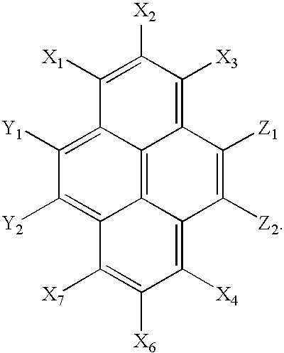
The pyrene based compound of the present invention has the following general formula (I): wherein Z1 represents a hydrogen atom, deuterium atom, oxygen atom, silicon atom, selenium atom, substituted or unsubstituted aryl group, substituted or unsubstituted heteroaryl group, substituted or unsubstituted aryl amine or a combination thereof, and Z2 represents a hydrogen or deuterium atom;wherein one of Y1 and Y2 represents a hydrogen atom, deuterium atom, oxygen atom, silicon atom, selenium atom, a substituted or unsubstituted aryl group, substituted or unsubstituted heteroaryl group, substituted or unsubstituted aryl amine or a combination thereof, and the other of Y1 and Y2 represents a hydrogen or deuterium atom;wherein X1 through X6 independently represent hydrogen atoms, deuterium atoms, alkyl groups or aryl groups, and at least one of X1 through X6 represents a bulky alkyl group or bulky aryl group; andwherein at least one of X1 through X6, Y1, Y2, Z1, and Z2 represents a deuteri...


PUM

PropertyMeasurementUnit
Structureaaaaaaaaaa

Abstract

A pyrene based compound and its use in an organic light emitting device (OLED) according to the following formula:
In the above formula, Z1 represents a hydrogen atom, deuterium atom, oxygen atom, silicon atom, selenium atom, substituted or unsubstituted aryl group, substituted or unsubstituted heteroaryl group, substituted or unsubstituted aryl amine or a combination thereof, and Z2 represents a hydrogen or deuterium atom. One of Y1 and Y2 represents a hydrogen atom, deuterium atom, oxygen atom, silicon atom, selenium atom, a substituted or unsubstituted aryl group, substituted or unsubstituted heteroaryl group, substituted or unsubstituted aryl amine or a combination thereof, and the other of Y1 and Y2 represents a hydrogen or deuterium atom. X1 through X6 independently represent hydrogen atoms, deuterium atoms, alkyl groups or aryl groups, and at least one of X1 through X6 represents a bulky alkyl group or bulky aryl group. Also, at least one of X1 through X6, Y1, Y2, Z1, and Z2 represents a deuterium atom. The pyrene based compounds of this invention are useful in emissive layers, hole transport layers, or electron transport layers of an organic light emitting device (OLED). Within these layers, the pyrene based compound can serve directly to constitute the layers or as a host and/or dopant.

Description

BACKGROUND OF THE INVENTION1. Field of the InventionThe present invention relates to pyrene based compounds and materials and their use in organic light emitting devices. These pyrene based compounds and materials can be used as the emissive layer, electron transport layer, hole transport layer or one or more of such layers, although their use as a blue emissive layer is preferred. These compounds can also be used as a host or dopant material for one or more of such layers.2. Description of the Related ArtOrganic light emitting devices (OLEDS) typically comprise a layer of emissive material between an anode and a cathode. When a bias is applied across the electrodes, positive charges (holes) and negative charges (electrons) are respectively injected from the anode and cathode into the emissive layer. The holes and the electrons form excitons in the emissive layer to emit light.Electrodes are chosen to facilitate charge injection. A transparent indium-tin-oxide (ITO) anode has a rela...

Claims


Application Information

Patent Timeline
IPC IPC(8): C09K11/06H05B33/14H05B33/12H01L51/00H01L51/50
CPCC09K11/06H01L51/0054H01L51/0058H05B33/14C09K2211/1011Y10S428/917H01L51/0067H01L51/0094H01L51/5012H01L51/006H10K85/622H10K85/626H10K85/633H10K85/654H10K85/40H10K50/11
Inventor LI, XIAO-CHANG CHARLESOKAMURA, YOSHIMASAUENO, KAZUNORITASHIRO, MASASHITASHIRO, HIDEKIPRAKASH, G. K. SURYA
Owner CANON KK
Why Eureka
Try Eureka