Air blown fiber (ABF) cable with low composite coefficient of thermal expansion

a composite coefficient and air blown fiber technology, applied in the direction of fibre mechanical structures, instruments, optics, etc., can solve the problems of optical transmission signal loss, air blown fiber (abf) tube cables installed in harsh weather environments, induced signal attenuation, etc., to prevent deterioration of polymer, improve thermal stability, and improve thermal stability

Inactive Publication Date: 2005-02-08
SUMITOMO ELECTRIC LIGHTWAVE +1
View PDF12 Cites 26 Cited by
  • Summary
  • Abstract
  • Description
  • Claims
  • Application Information

AI Technical Summary

Benefits of technology

In accordance with the present invention, applicants provide a novel air blown fiber optic tube cable with a low composite coefficient of thermal expansion. More specifically, the novel air blown fiber (ABF) optic tube cable assembly having improved thermal stability comprises an air blown fiber (ABF) tube within which one or more air blown optical fiber units can be installed, wherein the air blown fiber (ABF) tube is formed from a cross-linked polyolefin comprising a predetermined amount of an inorganic filler material such as chopped glass fiber, glass spheres, mica, talc, CaCO3 or the like, and/or a predetermined amount of polymeric filler material such as polyaramid, liquid crystal polymers or other engineering resins. An additional ultraviolet (UV) radiation stabilizerfiller may optionally be included, comprising a predetermined amount of carbon black or other suitable material which prevents deterioration of the polymer during exposure to ultraviolet (UV) radiation during the lifetime of the tube or cable. Another embodiment of the invention comprises a fiber optic cable assembly having improved therm

Problems solved by technology

Air blown fiber (ABF) tube cables installed in harsh weather environments, such as aerial outside plant cables, are subjected to extreme temperature and environmental conditions.
Significant shrinkage in the longitudinal axis direction of air blown fiber tubes may cause induced signal attenuation due to bending of the optical fibers housed in the tubes of the air blown fiber (ABF) tube cable.
Due to their small size, optical fibers have a relatively low buckling resistance resulting in bending of the optical fibers within the air-blown fiber (ABF) tubes which may cause optical tra

Method used


Image

  • Air blown fiber (ABF) cable with low composite coefficient of thermal expansion
  • Air blown fiber (ABF) cable with low composite coefficient of thermal expansion
  • Air blown fiber (ABF) cable with low composite coefficient of thermal expansion

Examples


Embodiment Construction

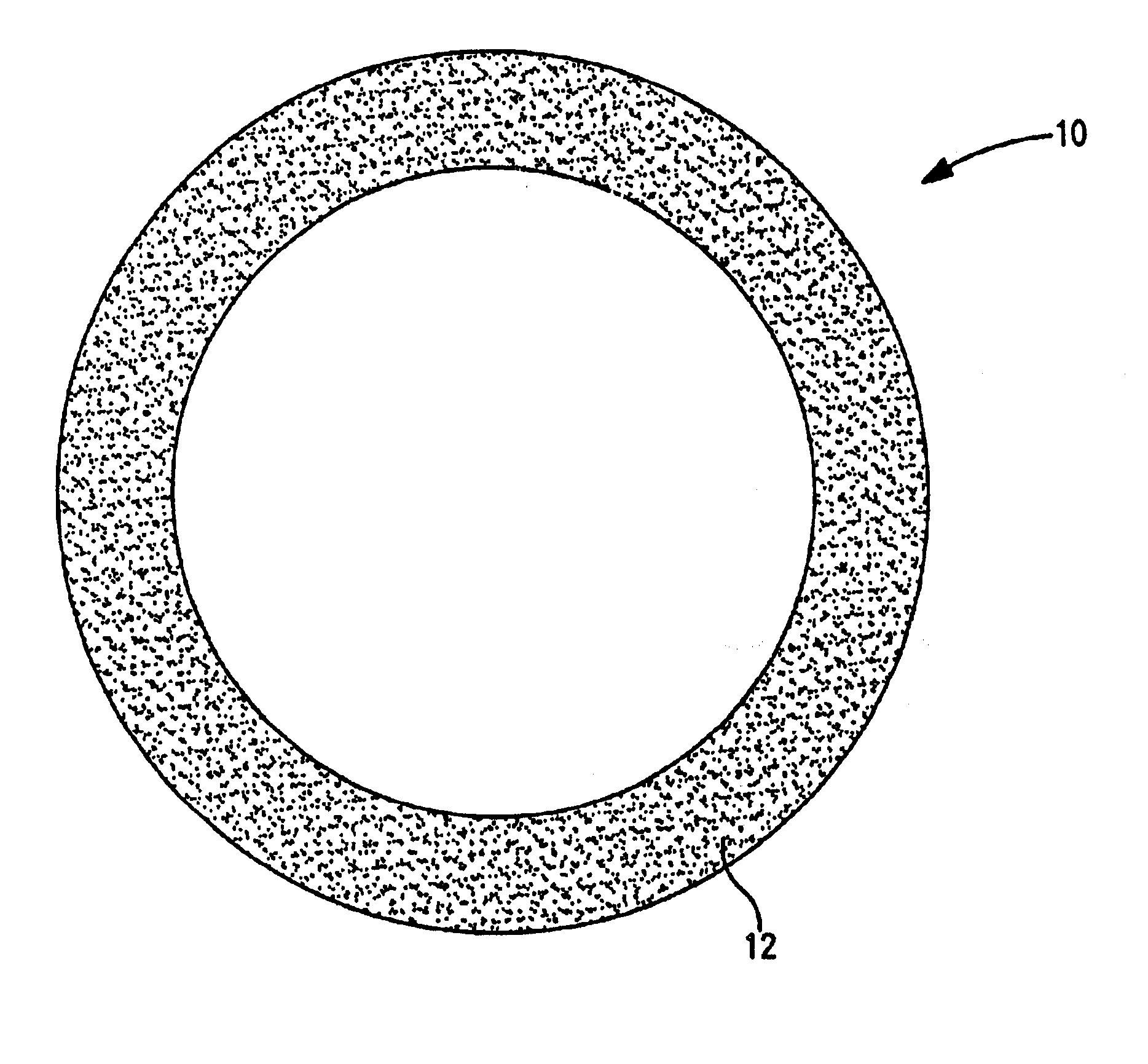
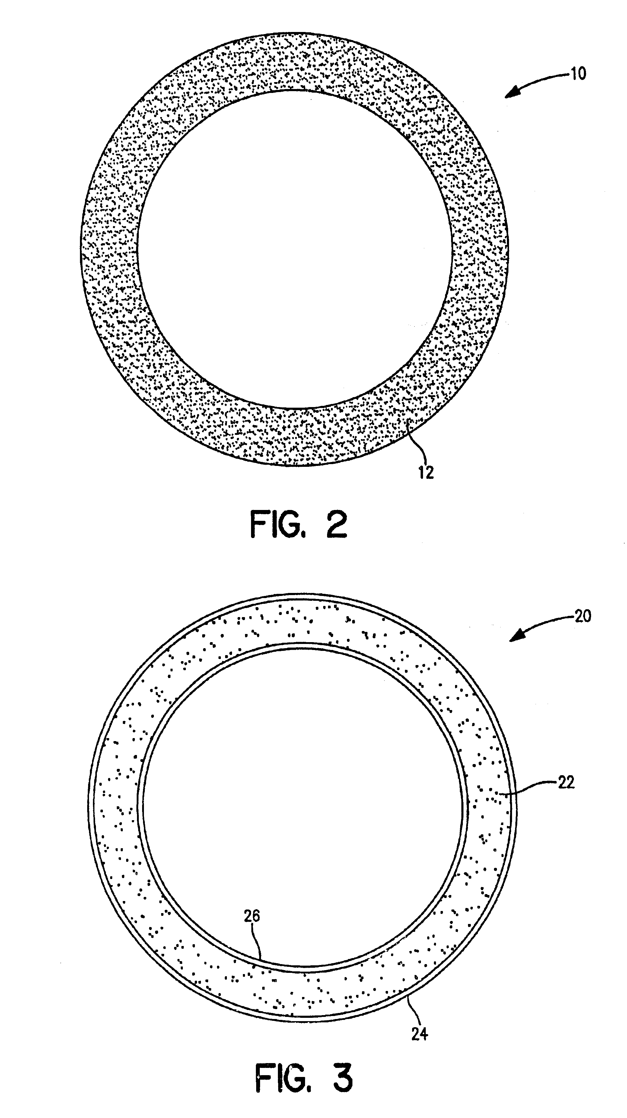
Preferred embodiments of the improved thermal stability air blown fiber (ABF) tube and the air blown fiber (ABF) tube cable in accordance with the present invention are described below with reference to FIGS. 2-6 of the drawings.

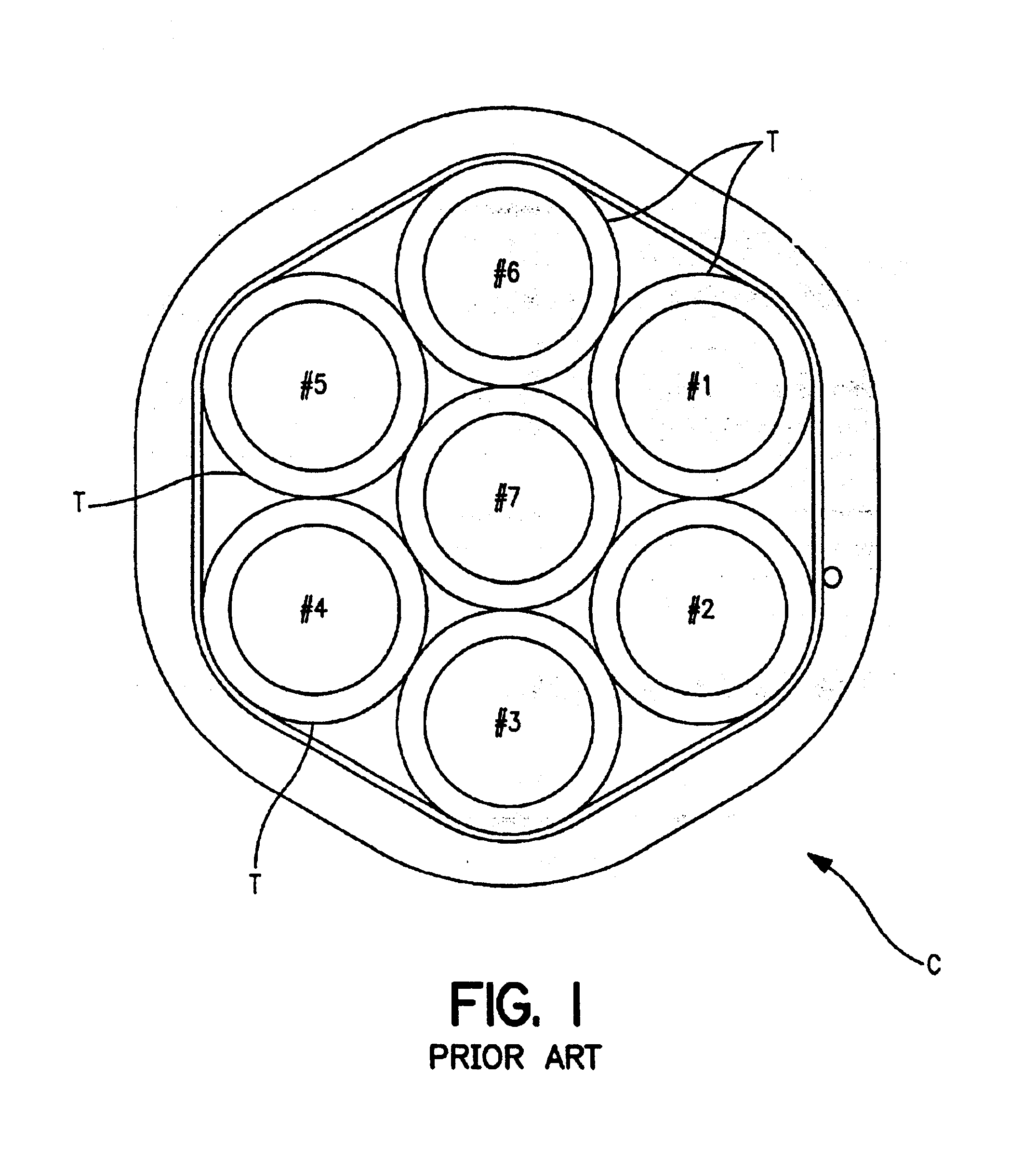
Referring now to FIG. 1, prior art blown fiber (ABF) tubes T are shown that can be used alone or in an air blown fiber (ABF) tube cable C as depicted in FIG. 1. Air blown fiber (ABF) tube T as shown is capable of supporting installation of multiple air blown optical fiber units and providing for cabling system upgrade capability. Prior art air blown fiber (ABF) tube T and tube cable C can be formed in a wide variety of sizes and tube counts in accordance with customer demands. For example, air blown fiber (ABF) tube cable C may comprise multiple 8 mm air blown fiber tubes T formed from polyethylene and jacketed with polyethylene to form a tube cable with a finished outside diameter of 29 mm. The shortcomings of the prior art air blown fiber (ABF) tubes T and...


PUM


Abstract

An air blown fiber tube cable having improved thermal stability in contrast to conventional air blown fiber (ABF) tube cables and within which one or more air blown optical fiber units can be installed. The air blown fiber tube is formed from a cross-linked polyolefin (preferably cross-linked high density polyethylene) comprising at least one non-polymer filler material having a coefficient of thermal expansion less than the coefficient of thermal expansion of said tube.

Description

TECHNICAL FIELDThe present invention relates to air blown fiber (ABF) tubes. More particularly, the invention relates to an air blown fiber (ABF) tube and tube cable jacket so as to provide both a low composite coefficient of thermal expansion and minimum post-extrusion shrinkage of the air blown fiber tube cable.RELATED ARTAir blown fiber (ABF) tube cables installed in harsh weather environments, such as aerial outside plant cables, are subjected to extreme temperature and environmental conditions. Low temperature shrinkage will ordinarily occur in the longitudinal axis direction of the tube and cable due to the relatively high coefficient of thermal expansion characteristic of the plastic used to manufacture conventional air blown fiber (ABF) tubes and cables. Significant shrinkage in the longitudinal axis direction of air blown fiber tubes may cause induced signal attenuation due to bending of the optical fibers housed in the tubes of the air blown fiber (ABF) tube cable. The opt...

Claims


Application Information

Patent Timeline
IPC IPC(8): G02B6/44
CPCG02B6/4401G02B6/4459G02B6/4485
Inventor CHASTAIN, SCOTT M.DIXON, TERRI L.GREGRICH, GLENN M.QUISTORFF, KEITHSCHULTZ, BRETT W.
Owner SUMITOMO ELECTRIC LIGHTWAVE
Why Eureka
Try Eureka