Magnetic disk comprising a first carbon overcoat having a high SP3 content and a second carbon overcoat having a low SP3 content

a technology of carbon protective overcoat and magnetic disk, which is applied in the direction of solid-state diffusion coating, instruments, record information storage, etc., can solve the problems of high sp3 carbon formed by chemical vapor deposition, failure of glide tests, etc., and achieve high sp3 content and resist wear and scratching

Inactive Publication Date: 2005-02-15
WESTERN DIGITAL TECH INC
View PDF31 Cites 82 Cited by
  • Summary
  • Abstract
  • Description
  • Claims
  • Application Information

AI Technical Summary

Benefits of technology

Of importarice, the high SP3 content protective layer is extremely hard, and resists wear and scratching. Because the second protective layer is so thin, it does not add substantially to the separation of the magnetic film within the disk and the read-write head.
It has further been discovered that although the second protective layer is extremely thin, the properties of the second protective layer control the manner in which the lubricant cooperates with the disk. In particular, although the second carbon layer is only 0.1 to 1 nm thick, the lubricant bonds with, and adheres to the second carbon layer in the same way that the lubricant would cooperate with the carbon on a conventional magnetic disk. The second carbon layer can mask any deleterious effects that the high SP3 content of the first carbon layer would otherwise have on the disk's interaction with the lubricant.

Problems solved by technology

Industry has devoted a large amount of time and effort trying to form appropriate carbon films to be deposited on magnetic disks as protective layers.
Merely by way of example, it has been discovered that when one tries to use the '107 type carbon and a perflouropolyether lubricant such as Z-dol (manufactured by Montedison Co. of Italy) mixed with an X1P additive, for reasons not well understood, the resulting disks tend to fail glide tests.
Thus, it is highly unexpected that the lubricant could interact with the carbon film in such a way as to cause a failure in a glide test where the glide height is eight times the lubricant thickness.
Certain forms of high SP3 carbon formed by chemical vapor deposition have been found to exhibit other problems, i.e. sensitivity to certain types of contaminants.

Method used


Image

  • Magnetic disk comprising a first carbon overcoat having a high SP3 content and a second carbon overcoat having a low SP3 content
  • Magnetic disk comprising a first carbon overcoat having a high SP3 content and a second carbon overcoat having a low SP3 content
  • Magnetic disk comprising a first carbon overcoat having a high SP3 content and a second carbon overcoat having a low SP3 content

Examples


Embodiment Construction

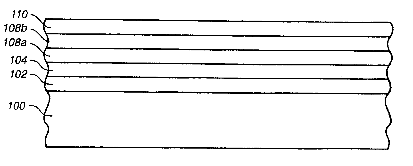
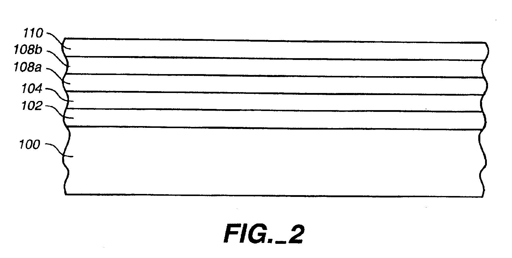
A process in accordance with the present invention comprises the following steps. First, a substrate 100 (FIG. 2) is provided. The substrate can be glass, glass ceramic, NiP-plated aluminum or other substrate material. Substrate 100 is then textured, e.g. using mechanical, laser or chemical techniques. (Such techniques are well known in the art.) One or more underlayers 102 (e.g. Cr, a Cr alloy, NiP, NiAl or other material) is deposited, e.g. by sputtering, onto substrate 100. Underlayer 102 can be about 10 to 30 nm thick.

One or more magnetic alloy layers 104 (e.g. a Co or Fe alloy) is deposited, e.g. by sputtering, onto underlayer 102. Magnetic layer 104 can be about 15 nm thick. In one embodiment, underlayer 102 and magnetic alloy layer 104 are formed using the method and materials described in U.S. patent application Ser. No. 08 / 874,753, filed by Bertero et al. on Dec. 4, 1997 and incorporated herein by reference.

A first overcoat 108a having a relatively high SP3 content is depos...


PUM

PropertyMeasurementUnit
thicknessaaaaaaaaaa
thickaaaaaaaaaa
thickaaaaaaaaaa

Abstract

A method for making a magnetic disk comprises forming first and second protective carbon layers on a magnetic layer. The first protective carbon layer is predominantly SP3 carbon. The second protective carbon layer comprises about 50% or less SP3 carbon. The second protective carbon layer is very thin, e.g. between 0.1 and 1.0 nm thick. A lubricant layer (e.g. a perfluoropolyether lubricant) is applied to the second protective carbon layer. The second protective carbon layer facilitates improved cooperation between lubricant and the disk.

Description

BACKGROUND OF THE INVENTIONThis invention pertains to methods for manufacturing magnetic disks comprising carbon protective overcoats and the resulting magnetic disks.FIG. 1 illustrates in cross section a magnetic disk 10 in a disk drive 12. Magnetic disk 10 comprises a substrate 14 (e.g. glass, glass ceramic, or NiP-plated aluminum), an underlayer 16 (e.g. Cr, a Cr alloy, NiP, NiAl or other appropriate material), a magnetic layer 18 (e.g. a Co alloy), and a protective overcoat 20 (e.g. hydrogen-doped carbon, nitrogen-doped carbon, or carbon doped with both hydrogen and nitrogen). A lubricant layer 22 (e.g. perfluoropolyether) is applied to protective overcoat 20.Magnetic disk 10 is mounted on a spindle that is rotated by a motor 24. A read-write head 26, mounted on a suspension 28, “flies” above the rotating disk. Head 26 comprises a slider including a hard Al2O3-TiC body 30 with a read-write element 32 formed on the trailing edge thereof. A carbon overcoat 34 is formed on the bott...

Claims


Application Information

Patent Timeline
Patent Type & Authority Patents(United States)
IPC IPC(8): C23C14/06C23C16/26G11B5/84G11B5/85G11B5/851C23C14/34G11B5/72
CPCC23C14/0605C23C16/26G11B5/8408G11B5/851G11B5/85Y10T428/24942Y10T428/30Y10T428/24975
Inventor JAIRSON, BRUCETSOI, CHING JACKIELIU, WENHASHIMOTO, SHIGETOYONG, ERIC WOO HOCKYAMASHITA, TSUTOMU TOM
Owner WESTERN DIGITAL TECH INC
Why Eureka
Try Eureka