
Power supply system for a packet-switched radio transmitter

Inactive Publication Date: 2005-02-15
BLACKBERRY LTD
View PDF13 Cites 33 Cited by
  • Summary
  • Abstract
  • Description
  • Claims
  • Application Information

AI Technical Summary

Benefits of technology

To improve upon the foregoing technology as disclosed in the current state-of-the-art, the present invention discloses an apparatus and method which allows a limited energy source (such as a low voltage battery stack or a low current computer auxiliary device power connection) to charge a high performance capacitive device, which in turn powers a low duty-cycle, high power load circuit (such as a packet-switched radio data transmitter). The load circuit's low duty-cycle allows the limited energy source to charge the high performance capacitive device sufficiently for periodic high power pulses. The high performance capacitive device provides “load-leveling” (i.e., an averaging out of the high transient currents drawn by the time varying, high power load), effectively isolating the input charging source from the large transient currents drawn by the load circuit such as during RF transmission by an RF transmitter.
The present invention provides many advantages over the presently known power distribution systems. Not all of these advantages are simultaneously required to practice the invention as claimed, and the following list is merely illustrative of the types of benefits that may be provided, alone or in combination, by the present invention. These advantages include: (1) increased battery life of the limited energy source; (2) reduced charging time; (3) reduced unit weight and size of the power distribution system; (4) reduced cost and complexity of the power supply circuitry; (5) simplified use and maintenance; (6) more predictable operation; (7) increased operational life of a unit employing the inventive system; and (8) reduced dollar costs for components.
In accordance with the present invention, a method is provided for extending the operational life of a battery device used to provide power to a low-duty cycle load circuit in a portable electronic device. The method comprises the steps of providing a capacitance network in the device; charging the capacitance network with the battery device; and providing energy to the load circuit, via the capacitance network, during the active portion of the duty cycle.
In another embodiment, a method is provided for extending the operational life of a battery device used to provide power to a low-duty cycle load circuit in a portable electronic device that comprises the steps of providing a capacitance network and a voltage regulator wherein the capacitance network comprises a first capacitance component and a second capacitance component. The method further comprises the steps of charging the second capacitive component with the battery device; powering the voltage regulator with the second capacitance component; charging the first capacitance component with the voltage regulator; and providing energy to the load circuit, via the capacitance network, during the active portion of the duty cycle.
In accordance with the present invention, a power management system for a portable electronic device having a low duty cycle transmitter is provided. The system comprises a limited energy source; a capacitive network coupled to the limited energy source and to the transmitter wherein the capacitance network comprises a first capacitance component and a second capacitance component; and a voltage regulator coupled to the capacitive network. In the system the limited energy source charges the second capacitive component, the second capacitive component provides energy to the voltage regulator, the voltage regulator charges the first capacitance component, and the capacitive network provides sufficient energy to power the transmitter when the transmitter is actively transmitting.

Problems solved by technology

Low duty-cycle radio frequency (“RF”) communication systems, such as digital, packet-switched RF transmission devices, typically include miniaturized low voltage power sources, and are characterized by relatively long time intervals between RF transmissions.
These systems, however, require that large bursts of power be delivered quickly for transmitter operation.
Thus, the power amplifier for a conventional packet-switched transmitter requires high input power only for short intervals, with relatively long low power quiescent periods in-between.
As a result, the “duty-cycle” of such a system, i.e., the percentage of the total cycle time taken by the active transmission time is quite low.
Despite the low duty-cycle of the system, the power amplifier for a conventional packet-switched transmitter produces a very high current load, drawing about 1000 milliamps (mA) or more for one second during transmission.
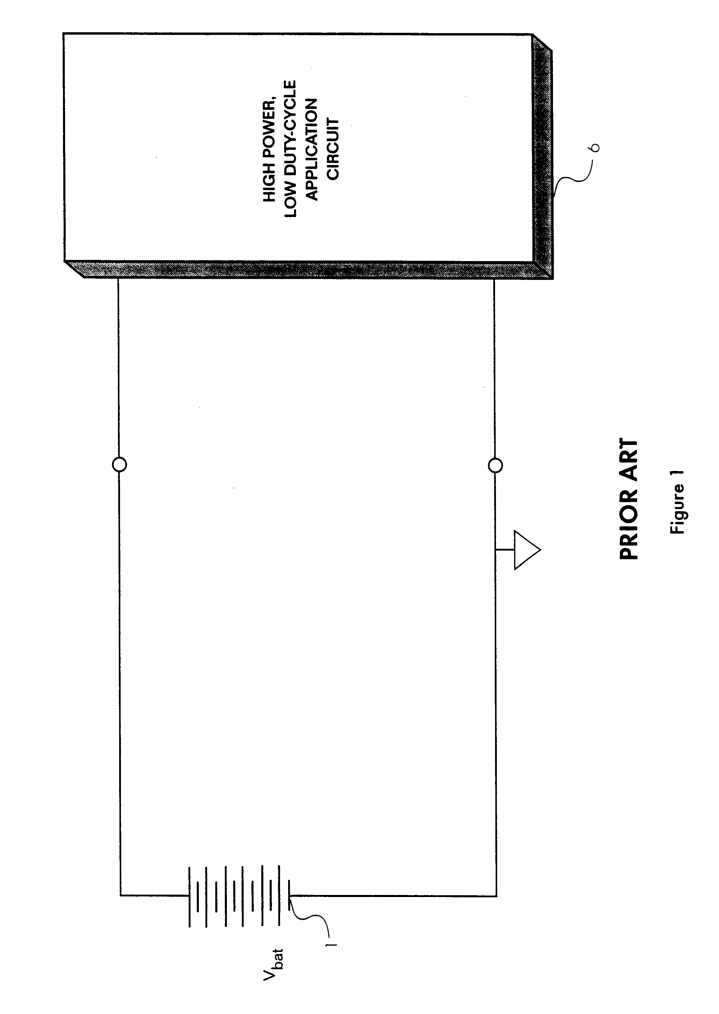
In prior art technologies, the RF transmitter was often powered directly from a conventional battery; however, the high power demands of the power amplifier imposed severe limitations on the type of battery technology that could be used.
Conventional carbon-based batteries typically could not provide sufficient instantaneous power for such a transmitter.
While a conventional alkaline cell could have powered the transmitter, the equivalent resistance of such a cell will climb rapidly as the cell is depleted.
This increasing resistance reduces the current that can be supplied to the transmitter and reduces the usable battery life.
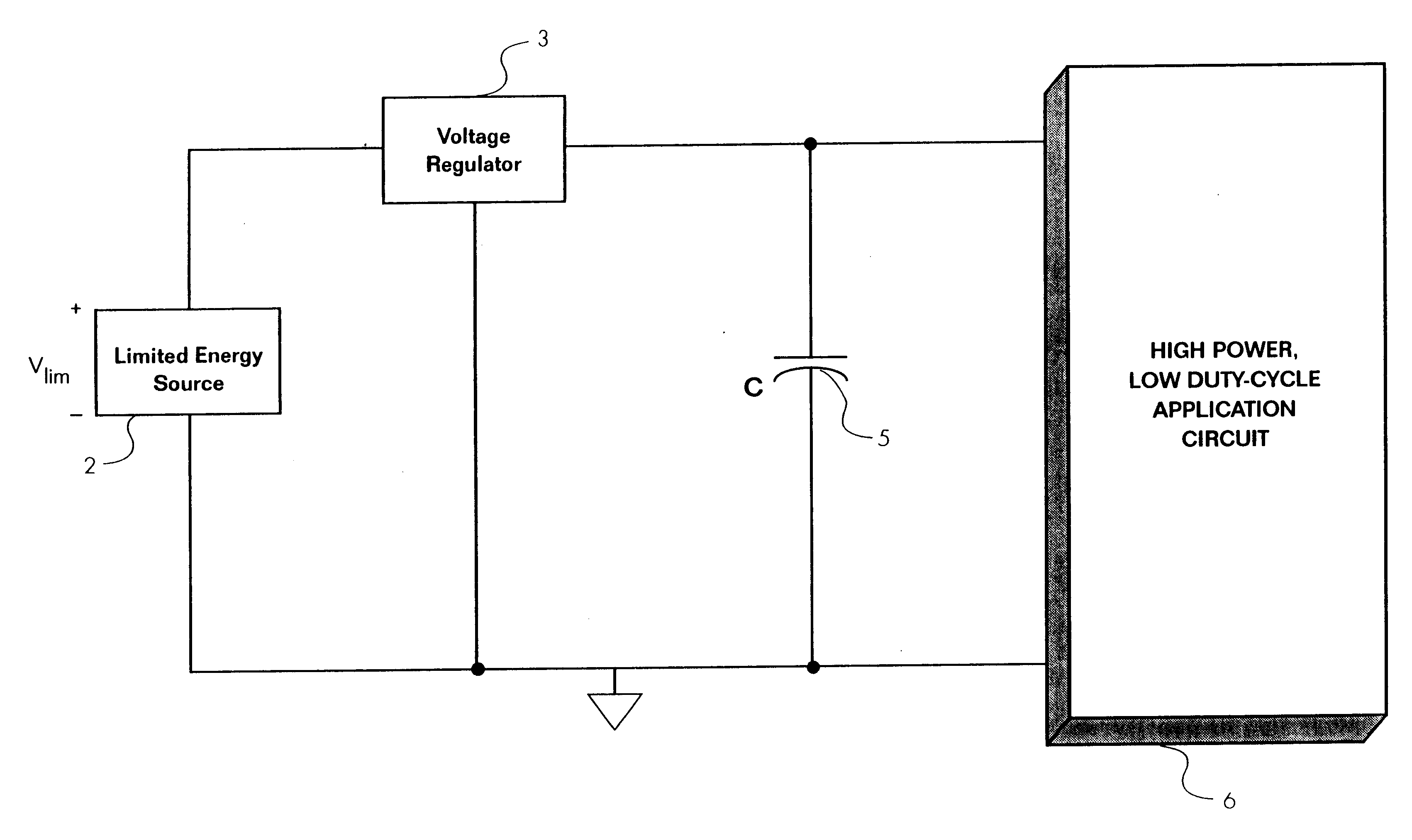
These systems were quite inefficient, however, because the battery stack would be overcharged, storing up far more power than that normally needed for sending a short packet-switched message.
Also, such power supply circuitry consumed space, was expensive, and was unnecessarily complex.
In addition, conventional rechargeable batteries, such as a Ni—Cd cell stack, have a long charge cycle, sometimes measured in hours, and could withstand only a limited number of charge cycles, perhaps about 300, before such batteries themselves would have to be replaced.
Other types of batteries exist that provide high energy storage, but are incompatible with conventional packet-switched RF transmission systems because of the high equivalent series resistance (“ESR”) of the cell.
Unfortunately, a lithium cell has an ESR of over 10 ohms, even when new, and can only deliver a peak instantaneous power of about 0.75 watts.
Because the typical RF transmitter requires 5 watts of input power and cannot tolerate an ESR of greater than 2 ohms, a cell such as the Ultralife® is not a viable power source despite its large storage capacity.
Similarly, a host computer auxiliary device power pin would be unsuitable to power a conventional packet-switched RF transmitter.
Because most host computers can supply only about 0.75 watts to a PCMCIA slot or other types of card plug-in modules, such a source of supply could not directly power a typical packet-switched transmitter, whose power amplifier would require 5 watts of instantaneous power.

Method used


Image

  • Power supply system for a packet-switched radio transmitter
  • Power supply system for a packet-switched radio transmitter
  • Power supply system for a packet-switched radio transmitter

Examples


Embodiment Construction

A high performance capacitive device useful with the present invention should possess high charge storage capacity with relatively low ESR in order to meet the input power needs of the typical transmitter power amplifier. For example, capacitive devices are now available that allow relatively large amounts of electrical energy to be temporarily stored and retrieved at much higher levels than standard batteries or conventional capacitors would allow. One class of such devices are specially constructed capacitors with very high storage capabilities referred to as super-capacitors.

A super-capacitor will generally have a rating of 1.0 farad or more of storage capacity, yet will only occupy the physical volume of a standard capacitor with only 0.002 farads of capacity. These devices are typically used to provide emergency backup power in computing applications, such as for CMOS microprocessors. The component miniaturization provided by super-capacitors is important if the power supply sy...


PUM


Abstract

An apparatus and method is disclosed which allow a limited energy source (such as a low voltage battery stack or a low current computer auxiliary device power connection) to charge a high performance capacitive device, which in turn powers a low duty-cycle, high power load circuit (such as a packet-switched radio data transmitter).

Description

FIELD OF THE INVENTIONThe present invention relates to the field of electrical power supply management circuitry, and in particular, to improved power supplies for low duty-cycle radio frequency (“RF”) communication systems, such as digital, packet-switched RF transmission devices.BACKGROUND OF THE INVENTIONLow duty-cycle radio frequency (“RF”) communication systems, such as digital, packet-switched RF transmission devices, typically include miniaturized low voltage power sources, and are characterized by relatively long time intervals between RF transmissions. These systems, however, require that large bursts of power be delivered quickly for transmitter operation. The present invention allows for substantial improvements in efficiency and effective battery life for such systems. In a conventional prior art digital RF communication system, the transmitter circuitry modulates a carrier signal with a binary signal, producing a transmitted RF sequence representing binary ones and zero...

Claims


Application Information

Patent Timeline
IPC IPC(8): H04B1/16H04B1/04
CPCH04B15/005H04B1/0475H02J7/345H04B2215/063
Inventor CARKNER, STEVENLOWLES, ROBERT J.NICKERSON, KENTSCHAAFF, CARL
Owner BLACKBERRY LTD
Learn More