Apparatus for enhancing the lifetime of stencil masks

a technology of masks and masks, applied in the field of masks for masks with lithography beams, can solve the problems of no suitable mask protection technology known to date, reduced membrane swelling, and substantial load on the membrane of stencil masks, and achieves the effect of effective sputtering cleaning

Inactive Publication Date: 2005-02-22
IMS NANOFABTION
View PDF7 Cites 83 Cited by
  • Summary
  • Abstract
  • Description
  • Claims
  • Application Information

AI Technical Summary

Benefits of technology

[0010]The deposition (first) and sputter (second) means may be realized in one device, such as the mask maintenance module of the preferred embodiment described below, or as separate devices within the lithography apparatus.
[0011]Preferably, the sputter means (second means) may comprise deflection means to adjust the direction of the sputter ion beam(s); the deflection means may be realised comprising an electrostatic ion-optical arrangement. It is further advantageous if sputtering is done in a scanning procedure over the area of the structure pattern. For this, the lateral size of the sputter ion beam(s), as measured in the plane of the mask, is suitably smaller than the dimension of the structure pattern area of the stencil mask by at least one order of magnitude. In order to provide for an effective sputtering cleaning in the regions between the apertures, the direction of the sputter ion beam forms an angle with the lithography beam (surface normal of mask) which is suitably at least 30°, prefer

Problems solved by technology

The irradiation of the stencil mask with the lithography beam brings about a substantial load to the stencil mask membrane, due to ion implantation causing crystal defects and mechanical effects such as swelling or shrinking, and due to sputtering from the membrane surface causing a continuous reduction of the membrane swelling.
For heavier ions, however, no suitable mask protection technology is known to date; on the other hand, IBL applications using heavy ions offer new technical applications, such as ion-patterning of storage media.
The main problem due to the ion irradiation even when protective layers are used is the effect of sputtering off, as it is now the protective layer (rather than the basic membrane material) whose thickness is continuously reduced even though the protective layer can be chosen so as to keep low the effect of sputtering.
Althou

Method used


Image

  • Apparatus for enhancing the lifetime of stencil masks
  • Apparatus for enhancing the lifetime of stencil masks
  • Apparatus for enhancing the lifetime of stencil masks

Examples


Embodiment Construction

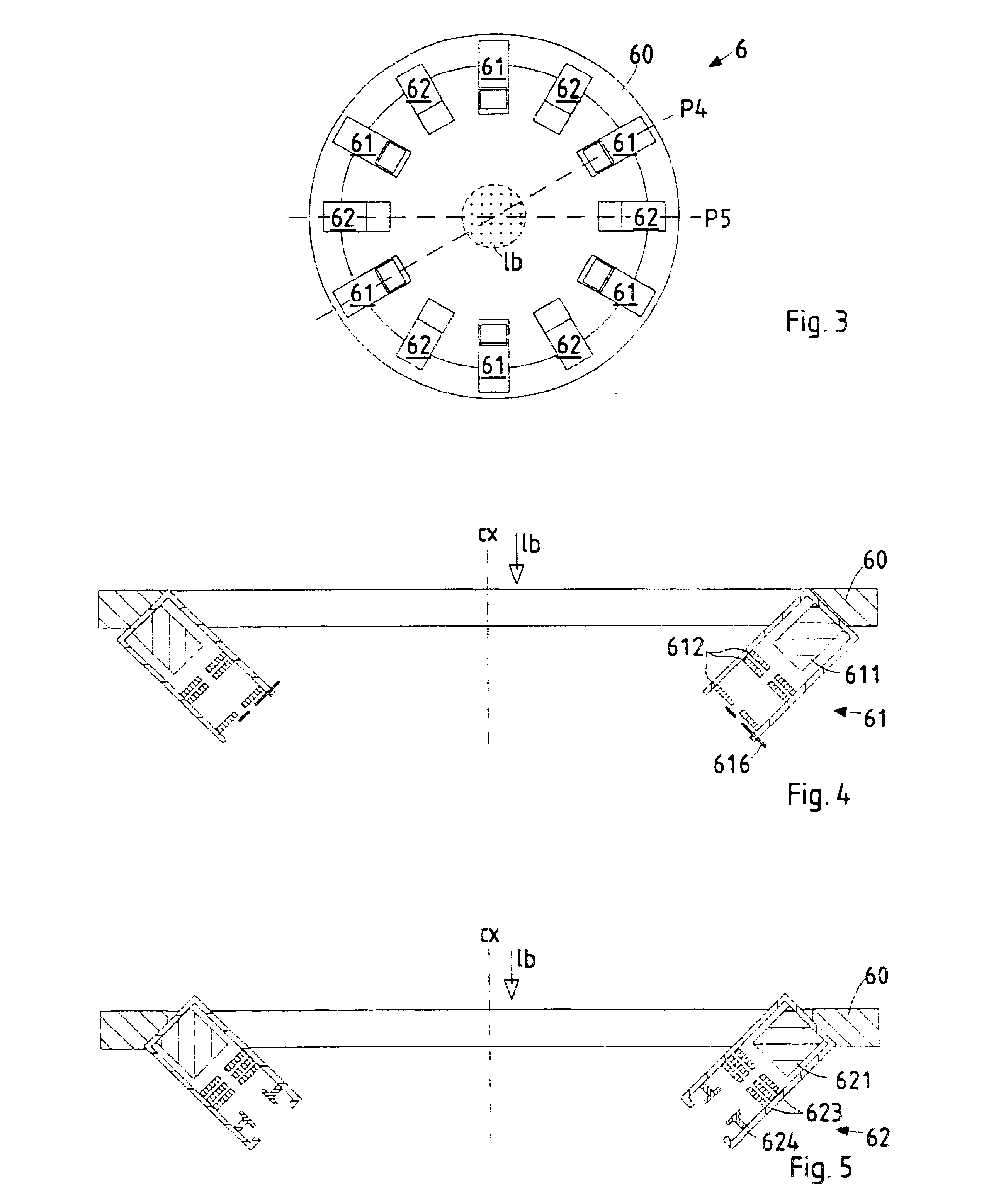
b class="d_n">[0018]FIG. 4 a detail of a sputter means used in the system of FIG. 3;

[0019]FIG. 5 a detail of a deposition means used in the system of FIG. 3;

[0020]FIG. 6 a detail of a mask structure at three stages (FIG. 6A to 6C);

[0021]FIG. 7 a lithography apparatus having a variant arrangement of the deposition means; and

[0022]FIG. 8 the sputter yield as a function of the angle of incidence.

DETAILED DESCRIPTION OF THE INVENTION

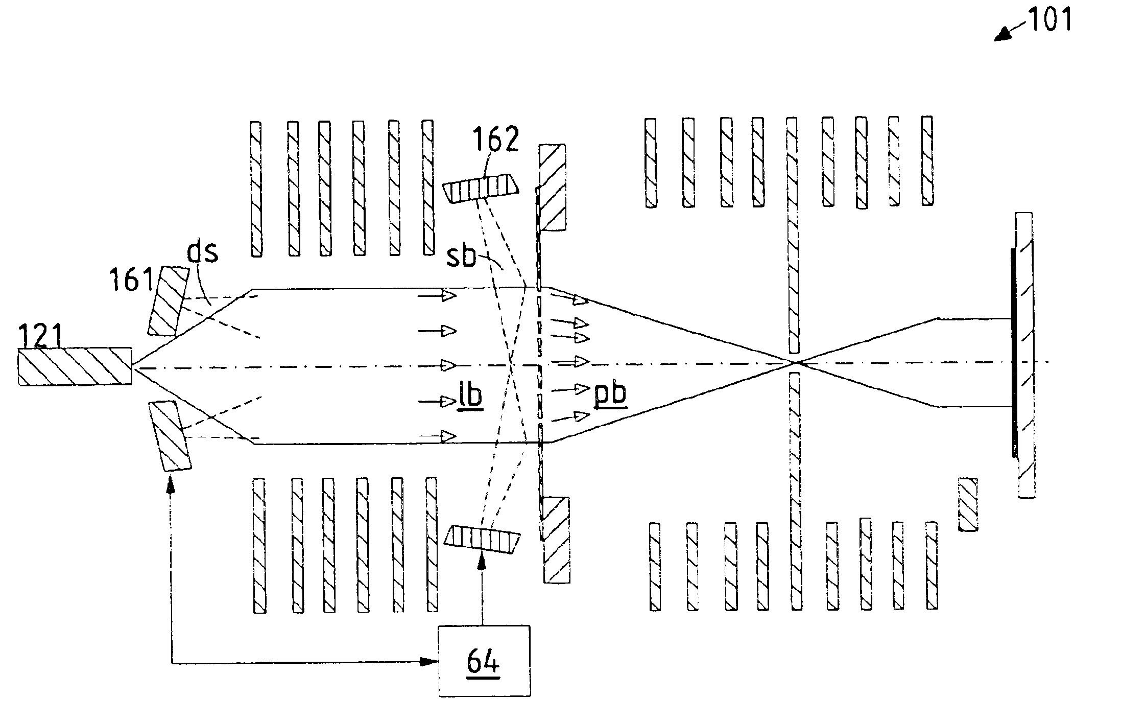
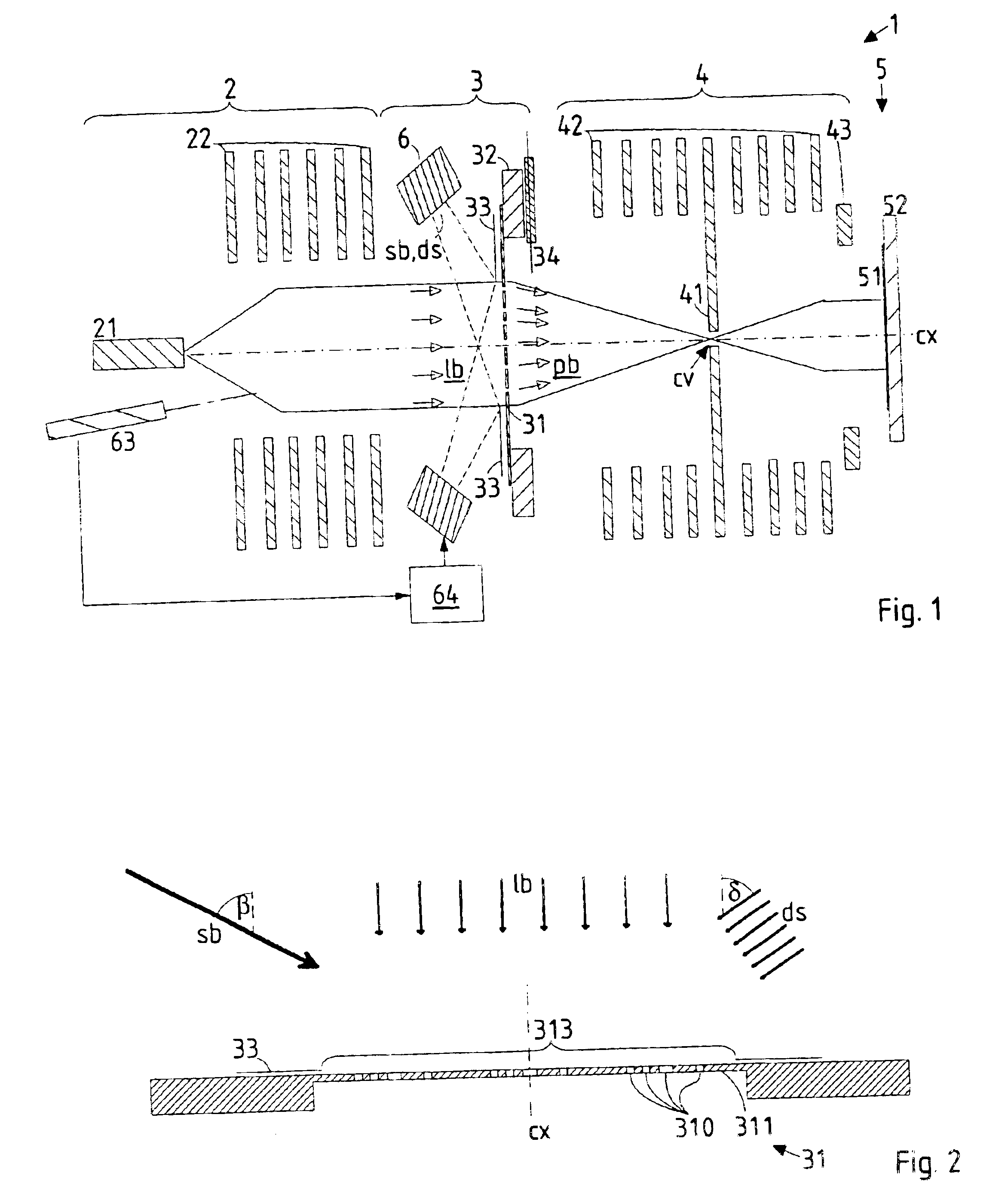
[0023]An overview of a lithographic apparatus according to a preferred embodiment of the invention is shown in FIG. 1. In the following, only those details are given as needed to disclose the invention; further details can be found in the EP 0 344 646 A2 (U.S. Pat. No. 4,985,634) of the applicant, which is herewith included by reference; a similar lay-out is described in the DE 196 27170 A1 (U.S. Pat. No. 5,742,062) of the applicant.

[0024]The main components of the lithography apparatus 1 are—corresponding to the direction of the lithography ion beam 1b,pb w...


PUM

PropertyMeasurementUnit
Angleaaaaaaaaaa
Angleaaaaaaaaaa
Thicknessaaaaaaaaaa

Abstract

An apparatus for masked ion-beam lithography comprises a mask maintenance module for prolongation of the lifetime of the stencil mask. The module comprises a deposition means for depositing material to the side of the mask irradiated by the lithography beam, with at least one deposition source being positioned in front of the mask, and further comprises a sputter means in which at least one sputter source, positioned in front of the mask holder means and outside the path of the lithography beam, produces a sputter ion beam directed to the mask in order to sputter off material from said mask in a scanning procedure and compensate for inhomogeneity of deposition.

Description

FIELD OF THE INVENTION AND DESCRIPTION OF PRIOR ART[0002]The invention relates to an apparatus for masked ion-beam lithography, in which a stencil mask is used to define a pattern on a substrate. In ion-beam lithography, a lithography beam consisting of energetic ions is radiated through the substantially flat stencil mask which comprises a stencil pattern made up of a plurality of transparent structures; the lithography beam then transfers the stencil pattern to a substrate. For this, the ion-beam lithography is provided with a mask holding means to position the stencil mask at an appropriate position in the path of the lithography beam.[0003]Stencil masks used in ion-beam lithography (IBL) are typically made of a silicon wafer or other disk of a suitable material, whose central area is thinned to form a thin membrane, and in the membrane a plurality of openings is formed which constitute the stencil pattern to be imaged onto the substrate realized as, e.g., a resist-covered semico...

Claims


Application Information

Patent Timeline
IPC IPC(8): C23C14/46C23C14/34C23C14/04C23C14/32G03F1/16H01L21/02H01J37/317H01L21/027C23C14/54G03F1/00
CPCB82Y10/00B82Y40/00C23C14/547H01J37/3174G03F1/82G03F1/20H01J2237/31794H01J2237/31755H01J2237/31788H01J37/3175
Inventor PLATZGUMMER, ELMARLOSCHNER, HANSSTENGL, GERHARD
Owner IMS NANOFABTION
Why Eureka
Try Eureka