Light source-optical fiber coupler

Inactive Publication Date: 2005-03-01
GOFOTON HLDG
View PDF4 Cites 12 Cited by
  • Summary
  • Abstract
  • Description
  • Claims
  • Application Information

AI Technical Summary

Benefits of technology

An object of the present invention is to provide a light source-optical fiber coupler which can optically couple a semiconduct

Problems solved by technology

Although the spherical lens can be produced most inexpensively, the spherical lens is insufficient to optically couple a semiconductor laser to a single mode optical fiber with a small loss.
Accordingly, particularly in the case of large item small volume production, there is a problem that the cost of the lens becomes high.
In this case, however, the distance between a laser chi

Method used


Image

  • Light source-optical fiber coupler
  • Light source-optical fiber coupler
  • Light source-optical fiber coupler

Examples


Embodiment Construction

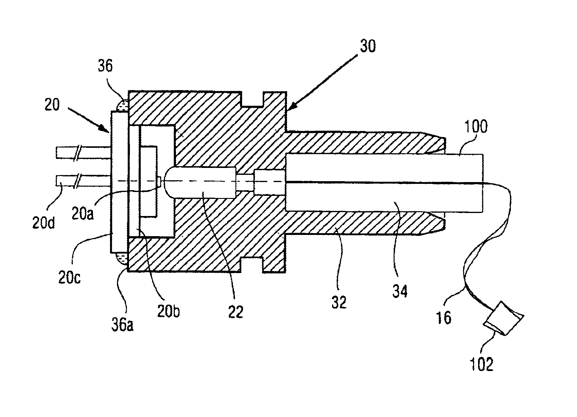
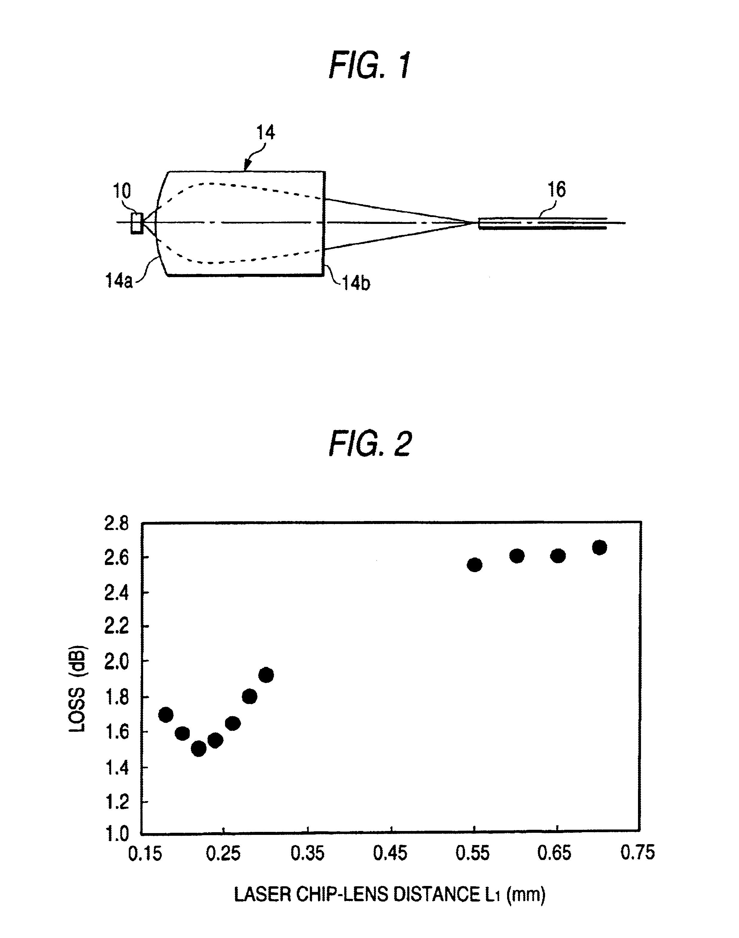
FIG. 1 is a basic configuration view showing a light source-optical fiber coupler according to the present invention. Light (diffuse luminous flux) emitted from a semiconductor laser (laser chip 10) is coupled to an end surface of a single mode optical fiber 16 by a gradient index rod lens 14. Here, the gradient index rod lens 14 is disposed so that the lens 14 has a semiconductor laser side end surface 14a shaped like a convex spherical surface, and an optical fiber side end surface 14b shaped like a flat surface. The semiconductor laser is formed as a structure in which neither cover glass nor cap is provided. Hence, the semiconductor laser is retained by the housing (not shown) in a state in which the laser chip 10 and the gradient index rod lens 14 are disposed close to each other. In addition, the optical fiber can be retained by the housing.

To make the semiconductor laser side numerical aperture NA2 large, the laser chip-rod lens distance L1 is selected to be not larger than 0...


PUM


Abstract

A light source-optical fiber coupler constituted by: a light source (such as a semiconductor laser chip 10); and a gradient index rod lens 14 for coupling diffuse luminous flux emitted from the light source to an end surface of an optical fiber (such as a single mode optical fiber 16). The gradient index rod lens has a light source side end surface shaped like a convex spherical surface, and an optical fiber side end surface shaped like a flat surface. The gradient index rod lens is retained by the housing in the condition that the light source (laser chip) and the gradient index rod lens are disposed close to each other. The distance between a surface of the laser chip and an end surface of the gradient index rod lens is preferably selected to be not larger than 0.3 mm and more preferably in a range of from about 0.2 mm to about 0.25 mm.

Description

BACKGROUND OF THE INVENTIONThe present invention relates to a light source-optical fiber coupler having a gradient index rod lens for coupling light emitted from a light source to an end surface of an optical fiber. More specifically, it relates to a light source-optical fiber coupler which has a gradient index rod lens having a light source side end surface shaped like a convex spherical surface, and an optical fiber side end surface shaped like a flat surface, and in which the light source and the gradient index rod lens are disposed close to each other to thereby make reduction in size possible.In optical communication or the like, diffuse luminous flux emitted from a light source such as a semiconductor laser is transmitted to a core of an optical fiber by a lens. Examples of the lens heretofore used for such optical coupling are a spherical lens, an aspherical lens, a gradient index rod lens, and so on.Although the spherical lens can be produced most inexpensively, the spherica...

Claims


Application Information

Patent Timeline
IPC IPC(8): G02B6/42G02B6/36H01S5/022
CPCG02B6/4206G02B6/4292
Inventor KOSHI, HIROSHISASAKI, YASUJI
Owner GOFOTON HLDG
Why Eureka
Try Eureka