Sheet for a thermal conductive substrate, a method for manufacturing the same, a thermal conductive substrate using the sheet and a method for manufacturing the same

a thermal conductive substrate and thermal radiation technology, applied in the field of circuit substrates, can solve the problems of low break down voltage, large noise, and difficult for metal base substrates and ceramic substrates to meet both performance and cost requirements, and achieve excellent thermal radiation properties

Inactive Publication Date: 2005-03-08
PANASONIC CORP
View PDF31 Cites 16 Cited by
  • Summary
  • Abstract
  • Description
  • Claims
  • Application Information

AI Technical Summary

Benefits of technology

The object of the present invention is to overcome the above mentioned problems and to provide a sheet for a thermally conductive substrate in which an inorganic filler can be filled in a resin at a high filler loading to form a thermally conductive module by a simple method, having (a) approximately the same coefficient of the thermal expansion in the plane direction of the substrate as that of a semiconductor, and (b) excellent thermal radiation property; a method for manufacturing the above mentioned sheet for a thermally conductive substrate; a thermally conductive substrate using the above mentioned sheet; and a method for manufacturing this thermally conductive substrate.
The first embodiment of the present invention basically relates to a thermally conductive sheet having flexibility, where an inorganic filler is added into a thermosetting resin in the not-hardened state at high density; the coefficient of thermal expansion in the plane direction is approximately the same as that of Si semiconductor; and high thermal conductivity is provided. In the thermally conductive sheet of the present invention, a high boiling point solvent is added into the thermosetting resin composition, or a thermosetting resin mixture containing a solid resin that is solid at room temperature and a liquid thermosetting resin that is liquid at room temperature, and films are formed by using a low boiling point solvent for mixing with inorganic filler. Consequently, in the thermally conductive sheet of the present invention, inorganic filler can be added at a high filler loading. Furthermore, the flexibility of the thermosetting resin of the thermally conductive sheet is manufactured in the not-hardened state, and, thus, molding the thermally conductive sheet into a desired shape at a low temperature and at a low pressure is possible. In addition, the thermally conductive substrate can be made rigid by hardening the thermosetting resin by thermal pressing. Also, a thermally conductive substrate on which a semiconductor can be simply and directly mounted can be obtained by the use of this thermally conductive sheet which is flexible.

Problems solved by technology

Therefore, as for the substrate of thin insulating layer, break down voltage is low, and the influence by the noise, too, is big.
It is difficult for the metal base substrate and ceramic substrate to satisfy both performance and cost requirements.
However, due to the high viscosity of the thermoplastic resin, it is difficult to injection mold such a module with a high filler content, and so the thermal radiation property of module is poor.
In particular, at the time of melting the thermoplastic resin at high temperature and kneading with filler, if there is too much filler, the melting viscosity is rapidly increased in a point that not only kneading but also injection molding is made impossible.
Moreover, the filler serves as an abrasives to abrade the metallic mold, and, thus, reduces the life of the mold.
Consequently, the content of the filler is limited, so that only lower thermal conductivity can be obtained as compared with the thermal conductivity of the ceramic substrate.

Method used


Image

  • Sheet for a thermal conductive substrate, a method for manufacturing the same, a thermal conductive substrate using the sheet and a method for manufacturing the same
  • Sheet for a thermal conductive substrate, a method for manufacturing the same, a thermal conductive substrate using the sheet and a method for manufacturing the same
  • Sheet for a thermal conductive substrate, a method for manufacturing the same, a thermal conductive substrate using the sheet and a method for manufacturing the same

Examples


example 1

In the formation of the thermally conductive sheet of the present invention; inorganic filler, thermosetting resin and solvent were mixed and alumina balls were further added into the above mixture so as to obtain a sufficient dispersion. The compositions of the thermally conductive sheet of this Example are shown in Table 1.

TABLE 1Thermosetting resinSolvent having aSheet(includingboiling point ofOther after driedExperimentInorganic Fillerhardener)not more than 150° C.additivesViscosityNo.NameVol. (wt %)NameVol. (wt %)NameVol. (wt %)*1*2*3(Pa · s)1aAl2O360Epoxy36Butyl4———1.5 × 10²resincalbitol1bAl2O370Epoxy28acetate2———3.3 × 10³resin(BCA)1cAl2O380Epoxy182———2.6 × 10⁴resin1dAl2O390Epoxy9.50.5———8.1 × 10⁴resin1eAl2O395Epoxy4.90.1———1.3 × 10⁵Resin*1: coloring agent *2: coupling agent *3: dispersing agent

Table 1 shows an evaluation of the performance of the thermally conductive sheet when the content of Al2O3 as an inorganic filler is changed. As Al2O3, “AL-33” having a particle diamet...

example 2

In this Example, a thermally conductive substrate in which the thermally conductive sheet was manufactured by the same method as in Example 1 and integrated with a lead frame will be explained. The compositions of the thermally conductive sheet used in this Example will be described hereinafter.(1) Inorganic filler: 90 weight % of Al2O3, “AS-40®” (the product of SHOWA DENKO K.K.) having a spherical shape and an average particle size of 12 μm.(2) Thermosetting resin: 9 weight % of cyanate ester resin, “AroCy M30®” (the product of Asahi-Ciba CO., Ltd.)(3) Solvent having a boiling point of not less than 150° C.: 0.5 weight % of butyl carbitol. (the first grade of chemical reagent of Kanto Chemical CO, Inc.).(4) Other additives: 0.3 weight % of “Carbon Black” (the product of Toyo-carbon CO., Ltd.), and 0.2 wt. % of dispersing agent, “PLYSURF F-208F®” (the product of DAI-ICHI SEIYAKU KOGYO CO., LTD.).

A thermally conductive sheet (a thickness was 770 μm) comprising the above mentioned com...

example 3

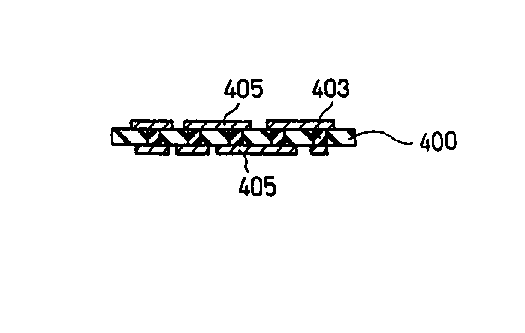
In this Example, a thermally conductive substrate will be explained, where the thermally conductive sheet was manufactured by the same method as in Example 1 and both sides of the sheet had metallic foil wiring layers and conductive resin composition was filled between the layers to electrically connect the layers. The compositions of the thermally conductive sheet used in this Example will be described hereinafter.(1) Inorganic filler: 90 weight % of Al2O3, “AS-40®” (the product of SHOWA DENKO K.K.) having a spherical shape and an average particle size of 12 μm.(2) Thermosetting resin: 9 weight % of “NRV-1010®” (the product of Japan REC CO., Ltd.), a mixture comprising 60 weight parts of brominated multifunctional epoxy resin as a main agent, 39.5 weight parts of bisphenol A nobolak resin as a hardener, and 0.5 weight parts of imidazol as a hardening accelerator.(3) Solvent having a boiling point of not less than 150° C.: 0.5 weight % of butyl carbitol (the first grade chemical rea...


PUM

PropertyMeasurementUnit
thicknessaaaaaaaaaa
particle diameteraaaaaaaaaa
viscosityaaaaaaaaaa

Abstract

A thermally conductive substrate having a structure in which inorganic filler for improving the thermal conductivity and thermosetting resin composition are included. The thermosetting resin composition has a flexibility in the not-hardened state, and becomes rigid after hardening. The thermally conductive substrate has excellent thermal radiation characteristics. The method of manufacturing the thermally conductive substrate includes: piling up (a) the thermally conductive sheets comprising 70 to 95 weight parts of an inorganic filler, and 4.9 to 28 weight parts of a thermosetting resin composition, the thermosetting resin composition comprising at least one thermosetting resin, a hardener and a hardening accelerator, and (b) lead frame on which a wiring is formed; thermal pressing the pile; filling the thermally conductive sheet to the surface of the lead frame; hardening the thermosetting resin; cutting excess sections of the thermally conductive substrate; and processing the bending perpendicularly for making a removable electrode.

Description

FIELD OF THE INVENTIONThe invention relates to a circuit substrate whose thermal radiation property is improved by a mixture of resin and inorganic filler. In particular, it relates to a high thermal radiation printed wiring board made of resin (thermally conductive substrate) for mounting electronic power devices.BACKGROUND OF THE INVENTIONRecently, as high performance and miniaturization of the electronic apparatus have been required, high density and high performance semiconductors have been sought. Consequently, circuit substrates for mounting thereof have also been required to be small and of high density. As a result, it is important to design circuit substrates taking the thermal radiation property into consideration. A well known technique for improving the thermal radiation property of circuit substrates, while using a printed circuit board made of glass-epoxy resin, is to use, a metal base substrate having a metal, for example, aluminum etc. and form a circuit pattern on o...

Claims


Application Information

Patent Timeline
Patent Type & Authority Patents(United States)
IPC IPC(8): B32B15/08H01L23/14H01L23/498H01L23/12H01L23/48H05K1/03H05K3/00H05K3/40H05K3/20H05K3/46H05K1/05
CPCB32B15/08H01L23/49833H01L23/49861H05K1/0373H01L23/145Y10T156/1034H01L2924/3011H05K1/056H05K3/0058H05K3/202H05K3/4069H05K3/4092H05K3/4614H05K3/4652H05K2201/0209H05K2201/0355Y10S428/901H01L2924/0002Y10T428/252Y10T428/265Y10T428/257Y10T428/24917Y10T156/1092Y10T428/258Y10T156/109Y10T428/25Y10T156/1056Y10T156/1057H01L2924/00Y10T428/31681Y10T428/31692B32B2311/12B32B2307/302B32B2305/74B32B27/20B32B2457/08
Inventor NAKATANI, SEIICHIHANDA, HIROYUKI
Owner PANASONIC CORP
Why Eureka
Try Eureka