Electrically controllable liquid crystal microstructures

a liquid crystal microstructure, electric control technology, applied in the direction of optics, instruments, diffraction gratings, etc., can solve the problems of cumbersome process of device construction, component failure to switch, and performance marred

Inactive Publication Date: 2005-03-08
KENT STATE UNIV
View PDF17 Cites 95 Cited by
  • Summary
  • Abstract
  • Description
  • Claims
  • Application Information

AI Technical Summary

Benefits of technology

It is an additional object of the present invention, as set forth above, to provide electrodes on each of the substrates, wherein each electrode is connected to an electrical power source which allows for switchin...

Problems solved by technology

But these components are not switchable which is essential for reprogrammable interconnects, angle multiplexers, data storage, and dynamically variable focal length devices.
Their performance is marred by factors such as high light scattering due to their internal structure and the need for high operating voltages.
These devices are built with cumbersome processes.
Furthermore, this method cannot be...

Method used


Image

  • Electrically controllable liquid crystal microstructures
  • Electrically controllable liquid crystal microstructures
  • Electrically controllable liquid crystal microstructures

Examples


Embodiment Construction

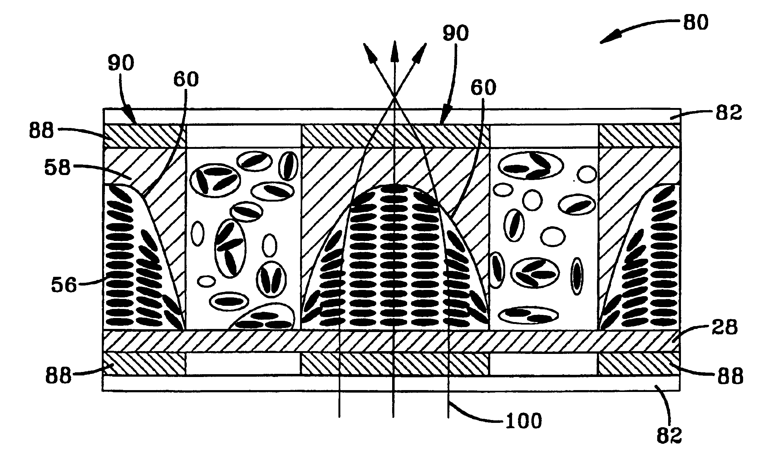
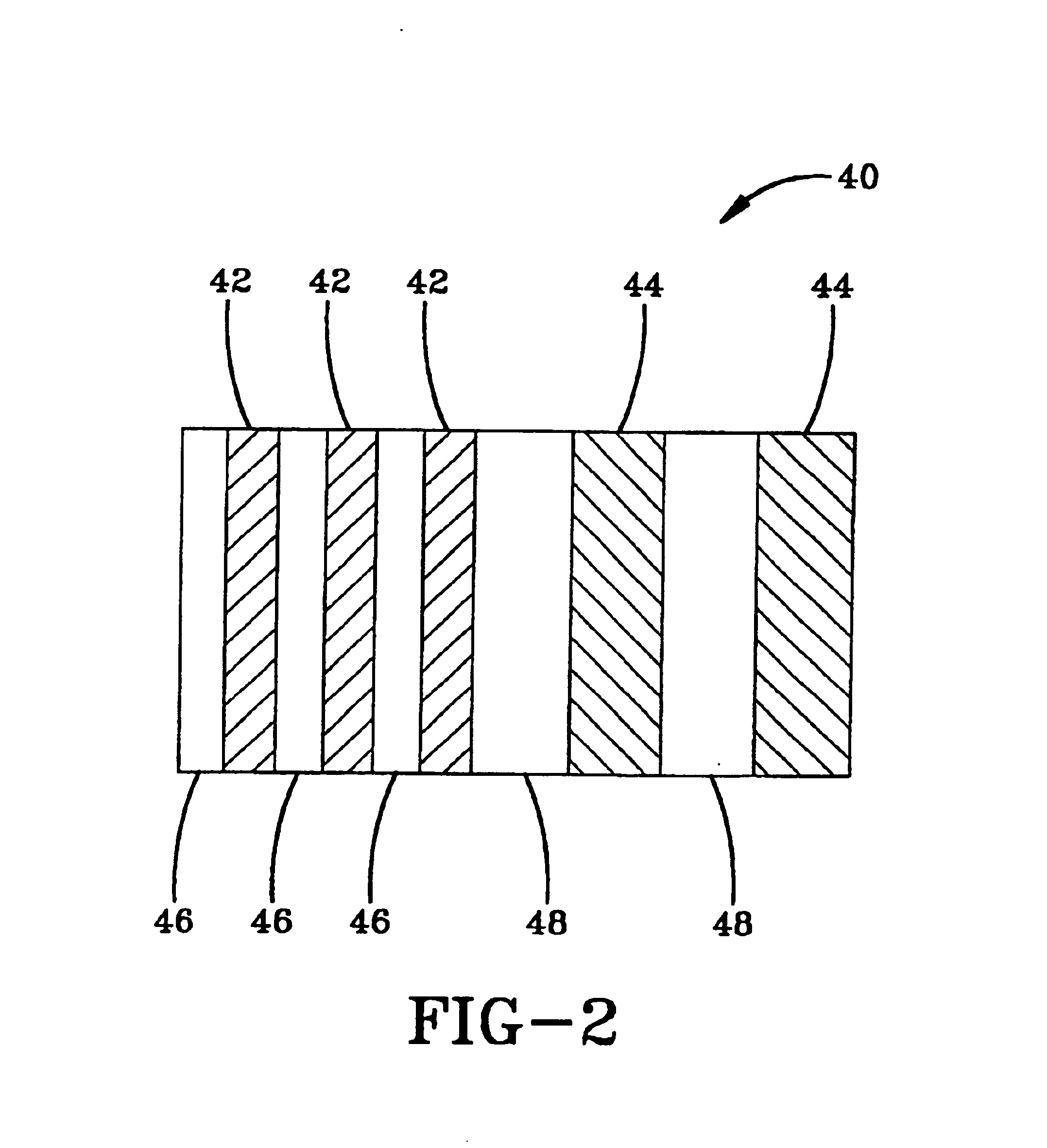
The present invention provides a way of building new electro-optic devices consisting of phase separated composite organic structures (PSCOS) for use as light modulating, beam steering, and focusing elements. The position, shape, and size as well as the uniformity of liquid crystal material and polymer rich regions is easily controlled by the methods disclosed herein. One can use nematic, cholesteric, smectic (e.g., chiral Sm A, ferroelectric, ferroelectric, and antiferroelectric), or any other liquid crystal (LC) to construct devices with the present invention.

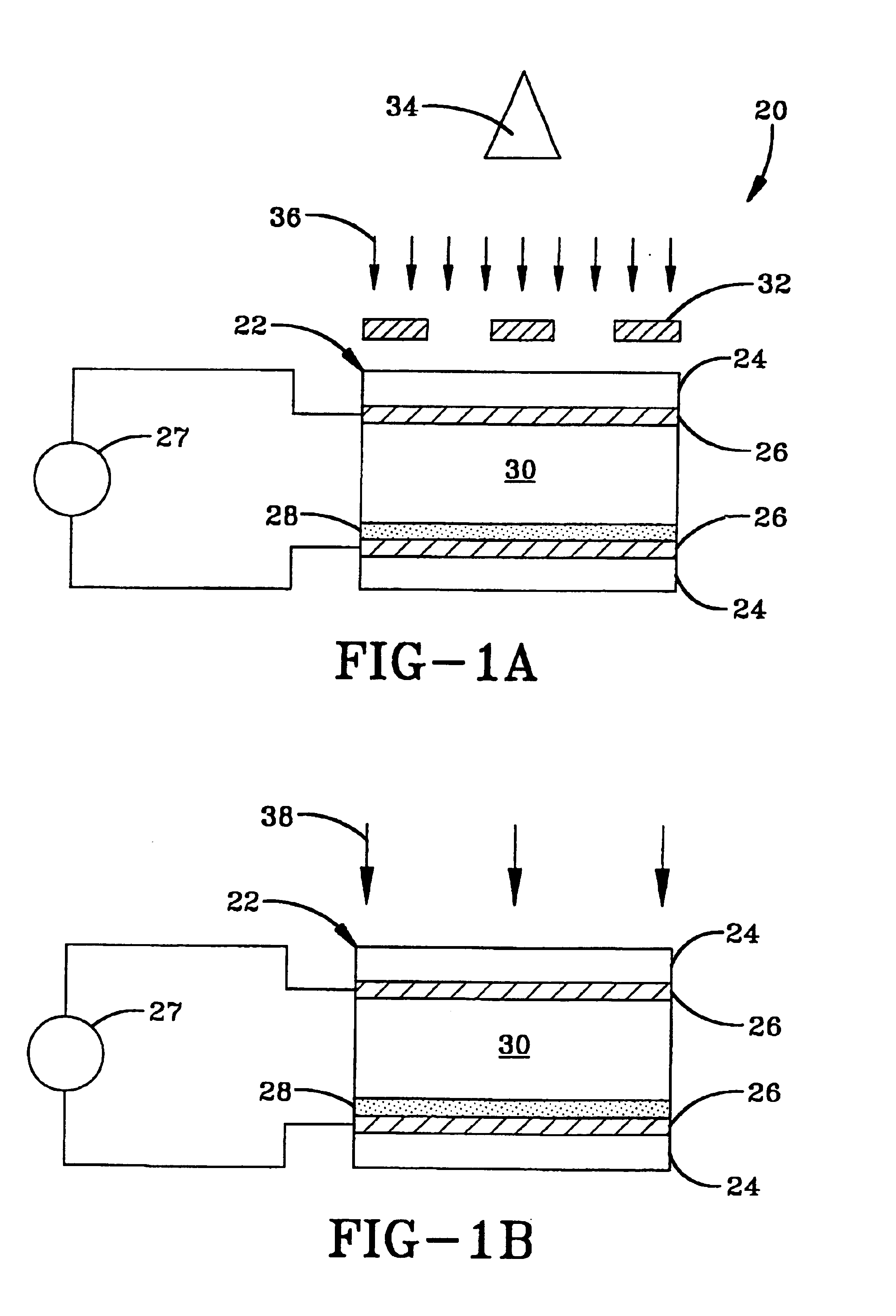
The devices of the present invention are fabricated by means of anisotropic polymerization induced phase separation (APIPS) of LC from its solution in a pre-polymer. The solution is placed between two substrates (glass or plastic) on which electrodes and alignment layer(s) were previously deposited depending upon the desired characteristics of the device. A photomask with desired pattern is placed between the UV source and th...


PUM


Abstract

This invention relates to methods of building rigid or flexible arrays of electro-optic devices. A phase separated composite structure technique yields adjacent regions of polymer and liquid crystal (LC) of specific architecture instead of a random dispersion of LC droplets. The above devices can be prepared by producing volutes of LC structure (56) next to a polymer area (58) using anisotropic phase separation of LC from a photopolymer. Initial by UV exposure. The shape, size and placement of these regions inside a cell becomes easily controllable with using optical mask or laser beam. The boundaries of LC volume can be controlled by controlling the chemical composition of the polymer and using an alignment layer (28).

Description

TECHNICAL FIELDThe present invention herein resides in the art of light modulating, shuttering, beam steering, and focusing devices that employ composite organic materials. In particular, this invention relates to a device in which a composite layer of optical material is formed by phase separation of a solution of prepolymer and low molecular weight organic fluid or a second crosslinkable prepolymer. It teaches specific techniques for fabricating required internal architecture of the composite material which, depending on the desired application, may be parallel films of liquid crystals and polymer or regions of liquid crystal of specific shape surrounded by polymer regions. Liquid crystal regions may be shaped and patterned to function as one-dimensional and two dimensional gratings, electrically addressable microlenses, or bounded and defined microstructures.BACKGROUND ARTElectro-optical devices are indispensable in this age of high-speed optical, and digital communications. Thes...

Claims


Application Information

Patent Timeline
IPC IPC(8): G02B3/00G02B5/18G02F1/13G02F1/29G02F1/1333
CPCG02B3/0006G02B3/0081G02F1/133377G02F1/29G02B5/1828G02B3/0056G02F2203/28G02F2001/294G02F1/294
Inventor KUMAR, SATYENDRAKIM, JAE-HOON
Owner KENT STATE UNIV
Why Eureka
Try Eureka