Sample introduction interface for analytical processing

Inactive Publication Date: 2005-03-15
NEWTON SCI +1
View PDF15 Cites 58 Cited by
  • Summary
  • Abstract
  • Description
  • Claims
  • Application Information

AI Technical Summary

Benefits of technology

[0022]Depending on which input technology is selected, measurements are performed in one of two regimes of operation: (i) high resolution, or (ii) high throughput. Coupling the AMS system to a liquid chromatograph, capillary electrophoresis (CE), or other liquid-phase sample separation technique results in high-resolution measurements. Reconfigur

Problems solved by technology

Therefore, the analysis of biological samples by AMS requires highly specialized sample preparation procedures that are not compatible with standard chromatographs.
This requirement has been a major impediment to the use of AMS in the biomedical sciences.
The coupling of a liquid chromatograph (LC) to an AMS is particularly challenging because the interface must provide for the efficient conversion of biological molecules in a variety of solvents into CO2 or H2, and must do so with high sample transfer efficiency, good peak shape retention, and minimal contamination with naturally occurring 14C or 3H from other sources such as solvents and previous samples.
However, the applicability of GC-AMS is limited to volatile substances.
For these reasons, accurate 14C detection by AMS without solvent removal is extremely difficult.
However, there are no provisions for desolvation, and the molecular dissociation and ion formation occur in the same process in the ion source itself.
However, none of these disclosed designs include a provision for desolvation.
An additional disadvantage of the direct coupling of a liquid chromatograph to the ion source syst

Method used


Image

  • Sample introduction interface for analytical processing
  • Sample introduction interface for analytical processing
  • Sample introduction interface for analytical processing

Examples


fourth embodiment

[0033]FIGS. 7 and 8A-8D illustrate the present invention, coupling of laser-assisted desorption / ionization to a converter and then to the AMS;

fifth embodiment

[0034]FIGS. 9A-9B illustrates the invention, the laser-induced sample conversion method;

[0035]FIGS. 10A-10B illustrate the laser-induced sample conversion method for conversion of organic samples to CO2 for AMS analysis or other applications;

[0036]FIGS. 11A-11C illustrate an example of apparatus in which sample is moved past a fixed laser beam;

[0037]FIGS. 12A-12B illustrate the laser-induced sample conversion method for conversion of hydrogen-containing samples to H2 for AMS analysis or other applications;

[0038]FIGS. 13A-13B illustrate yet another embodiment for the conversion of sample in an AMS ion source; and

[0039]FIGS. 14A-14B illustrate sample conversion in the AMS ion source using a Cs ion beam; and

[0040]FIGS. 15 and 16 illustrate interfaces for continuous processing.

DETAILED DESCRIPTION OF THE INVENTION

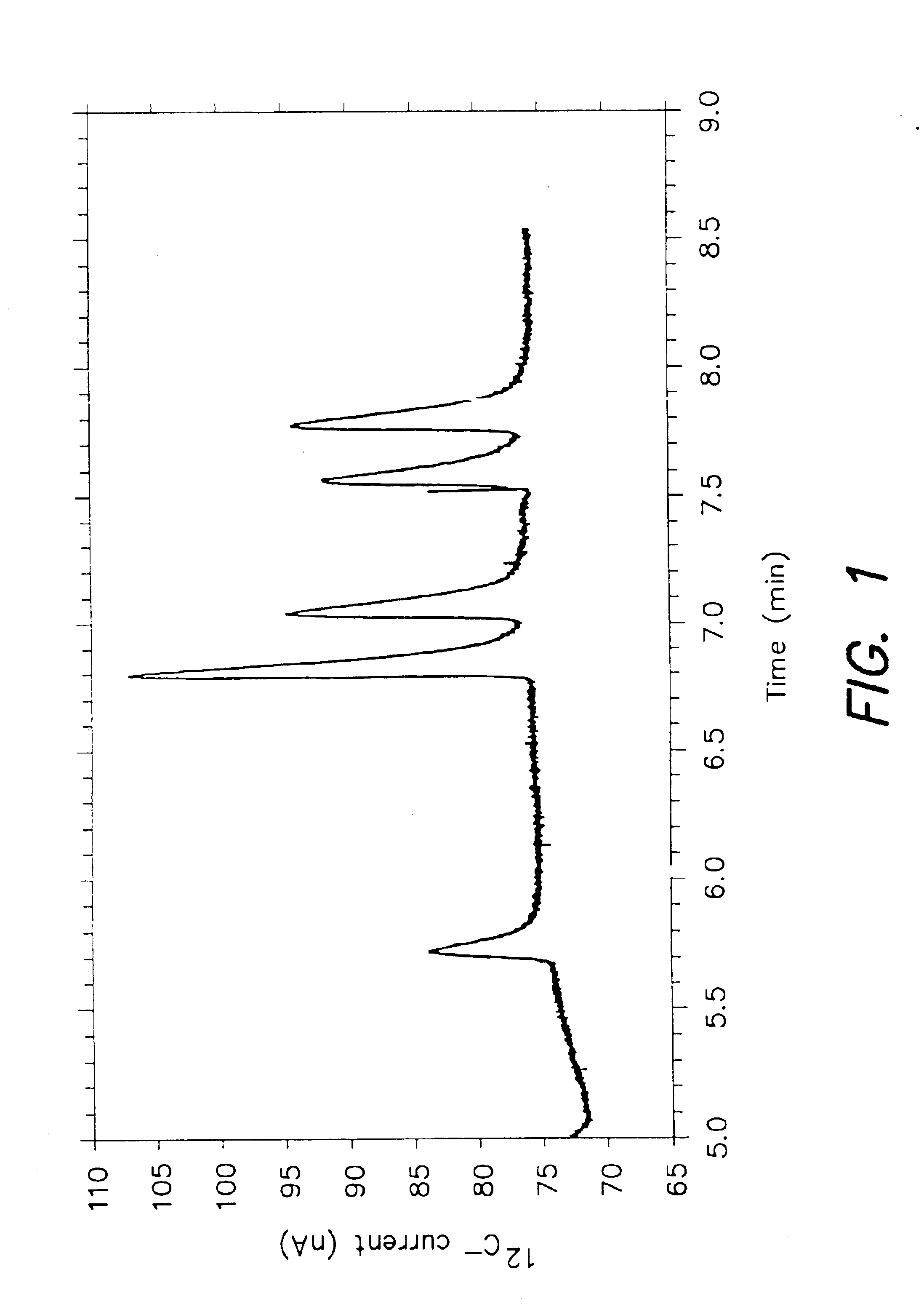
[0041]FIG. 1 displays detection of an equimolar carbon standard with the AMS ion source. A mixture containing six compounds was injected into a GC-AMS interface, comprising a H...

second embodiment

[0075]An example of the invention is the conversion of carbon or hydrogen in complex samples into C− or H− in a cesium-sputter negative ion source, as illustrated in FIGS. 14A and 14B. Cesium sputter ion sources of this type are described in publications: Nucl. Instr. and Method B52:517 (1990); and Nucl. Instrum. Meth. Phys. Res. B92:445 (1994). Sample 1400 is applied to a surface of a substrate 1402 that is then moved through a focused Cs ion beam 1404 within the ion source chamber. In contrast to the conventional practice of converting the sample to solid graphite prior to introduction into the ion source chamber, the present invention introduces the sample in its native form, either as a solid or a liquid, in accordance with the techniques described above. That is, the step of dispensing sample onto the substrate is performed outside of the ion source chamber, and the substrate 1402 is then introduced into the ion source chamber and translated relative to the Cs beam 1404. This s...


PUM


Abstract

An interface for introducing a non-gaseous sample as a predetermined gaseous form into an accelerator mass spectrometer which comprises a nebulizer that receives the non-gaseous sample to provide a fine spray of the sample, a converter that receives at least a portion of said fine spray and converts the desired elements to the predetermined gaseous form and a flow line that transports the predetermined gaseous form to the accelerator mass spectrometer.

Description

CROSS REFERENCE TO RELATED APPLICATIONS[0002]This application is a continuation-in-part of application designated Ser. No. 09 / 648,053 filed Aug. 25, 2000 now abandoned and entitled “Sample Introduction Interface for Accelerator Mass Spectrometry”, and claims priority from the provisional application designated Ser. No. 60 / 227,711 filed Aug. 24, 2000 entitled “Sample Introduction Interface” and the provisional application designated Ser. No. 60 / 227,839 filed Aug. 25, 2000 entitled “Sample Introduction Interface”. Each of these applications is hereby incorporated by reference.[0003]This invention was made with government support under Grant Number CA66400, awarded by NIH and Grant Number DMI-9634259 awarded by NSF. The government has certain rights in the invention.BACKGROUND OF THE INVENTION[0004]The present invention relates to a method and apparatus for the introduction of selected chemical elements present in solid or liquid samples into an accelerator mass spectrometry (AMS) syst...

Claims


Application Information

Patent Timeline
IPC IPC(8): G01N30/00G01N30/72H01J49/02H01J49/04G01N30/84
CPCG01N30/7233H01J49/0463H01J49/0445G01N2030/8405
Inventor HUGHEY, BARBARA J.SKIPPER, PAUL L.WISHNOK, JOHN S.SHEFER, RUTH E.FRIED, NAOMI A.MEHL, JOHN T.TANNENBAUM, STEVEN R.
Owner NEWTON SCI
Why Eureka
Try Eureka