Dual-wavelength passive self-modulated mode-locked semiconductor laser diode

a semiconductor laser and self-modulation technology, applied in the direction of lasers, semiconductor lasers, optical resonator shape and construction, etc., can solve the problems of laser diode irreversible damage, laser diode inoperability, sharp emission spike (or pulse),

Inactive Publication Date: 2005-03-15
UNIV LAVAL
View PDF18 Cites 7 Cited by
  • Summary
  • Abstract
  • Description
  • Claims
  • Application Information

AI Technical Summary

Benefits of technology

According to one aspect of the invention, a method of generating laser pulses using a semiconductor laser diode as a lasing amplification medium of an extended laser cavity is provided. The method includes a sequence of steps. A lasing-threshold input current is provided to the semiconductor laser diode. Elements making up the laser cavity are aligned for maximum laser output. The input current is increased beyond the lasing threshold and at least one of the elements making the laser cavity is slightly misaligned. Passive self-modulated mode-locked operation of the semiconductor laser diode is achieved.

Problems solved by technology

Constructive interference of all oscillating lasing modes takes place over a short period of time, giving rise to a sharp emission spike (or a pulse).
Destructive interference between all oscillating lasing modes takes place at all other instants, producing a weak or a vanishingly small output signal.
Fulfilling such conditions generally leads to an irreversible damage imparted to and eventual inoperability of the laser diode.
However the pulses produced through passive mode-locking cannot be synchronized with respect to any signal.
One can benefit from the advantages of both modulation techniques, but at the price of an added complexity.
In guided-wave structures such as semiconductor laser diodes, self-focusing is not effective as a mode-locking mechanism since it represents only a weak effect in comparison with the guiding effect produced by the guided-wave structure itself.
This is probably why passive self-modulation mode-locking, based upon self-focusing is not operational in semiconductor laser diodes.

Method used


Image

  • Dual-wavelength passive self-modulated mode-locked semiconductor laser diode
  • Dual-wavelength passive self-modulated mode-locked semiconductor laser diode
  • Dual-wavelength passive self-modulated mode-locked semiconductor laser diode

Examples


Embodiment Construction

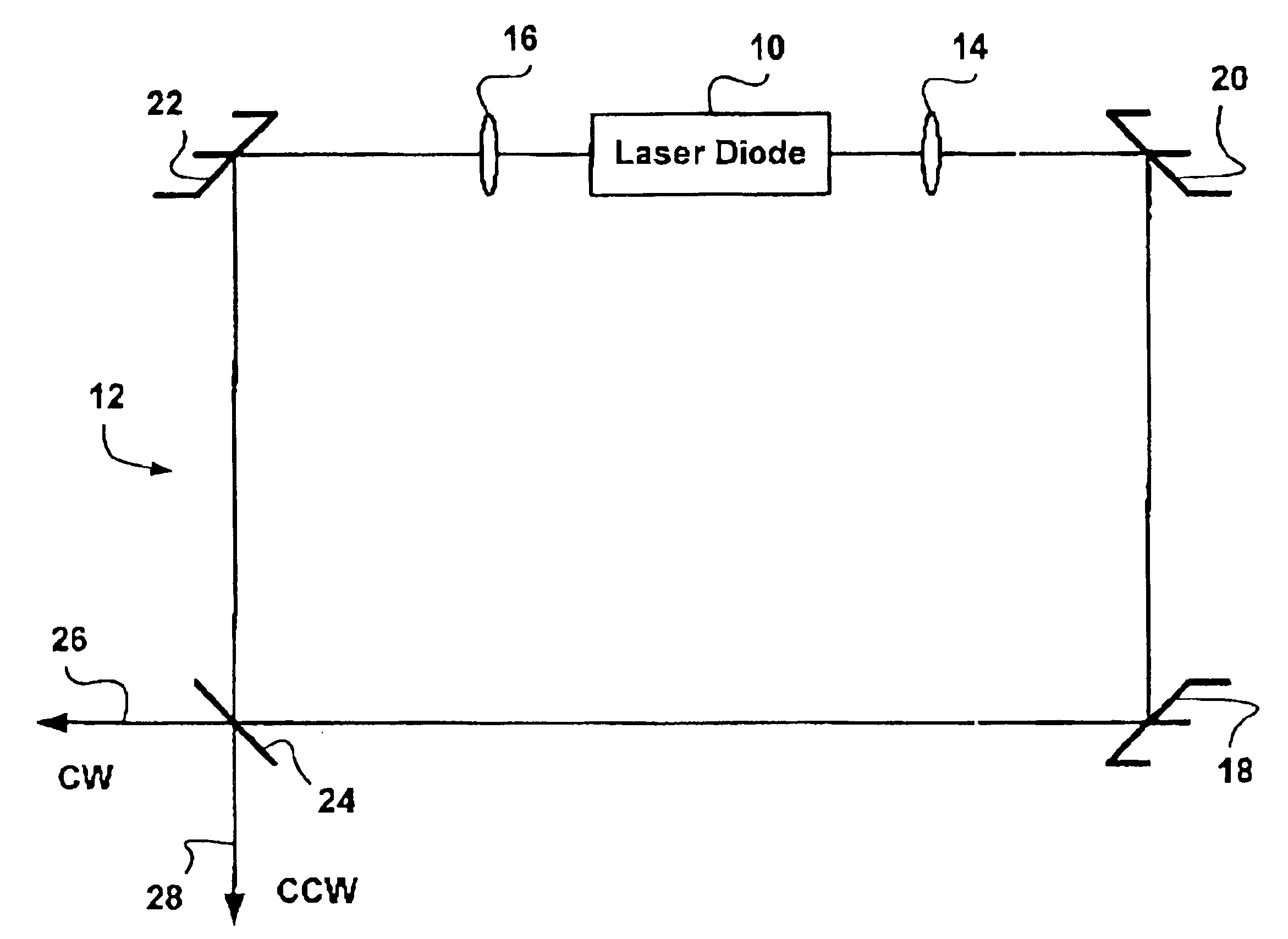
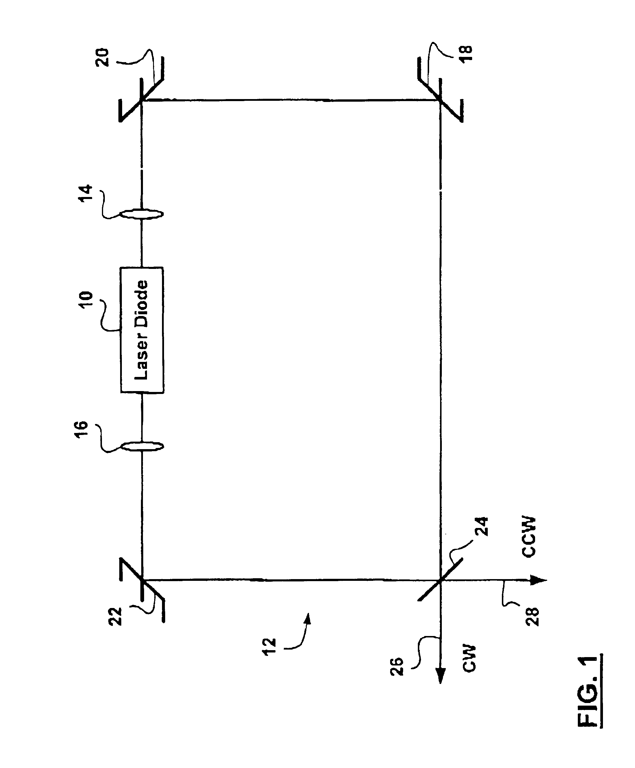
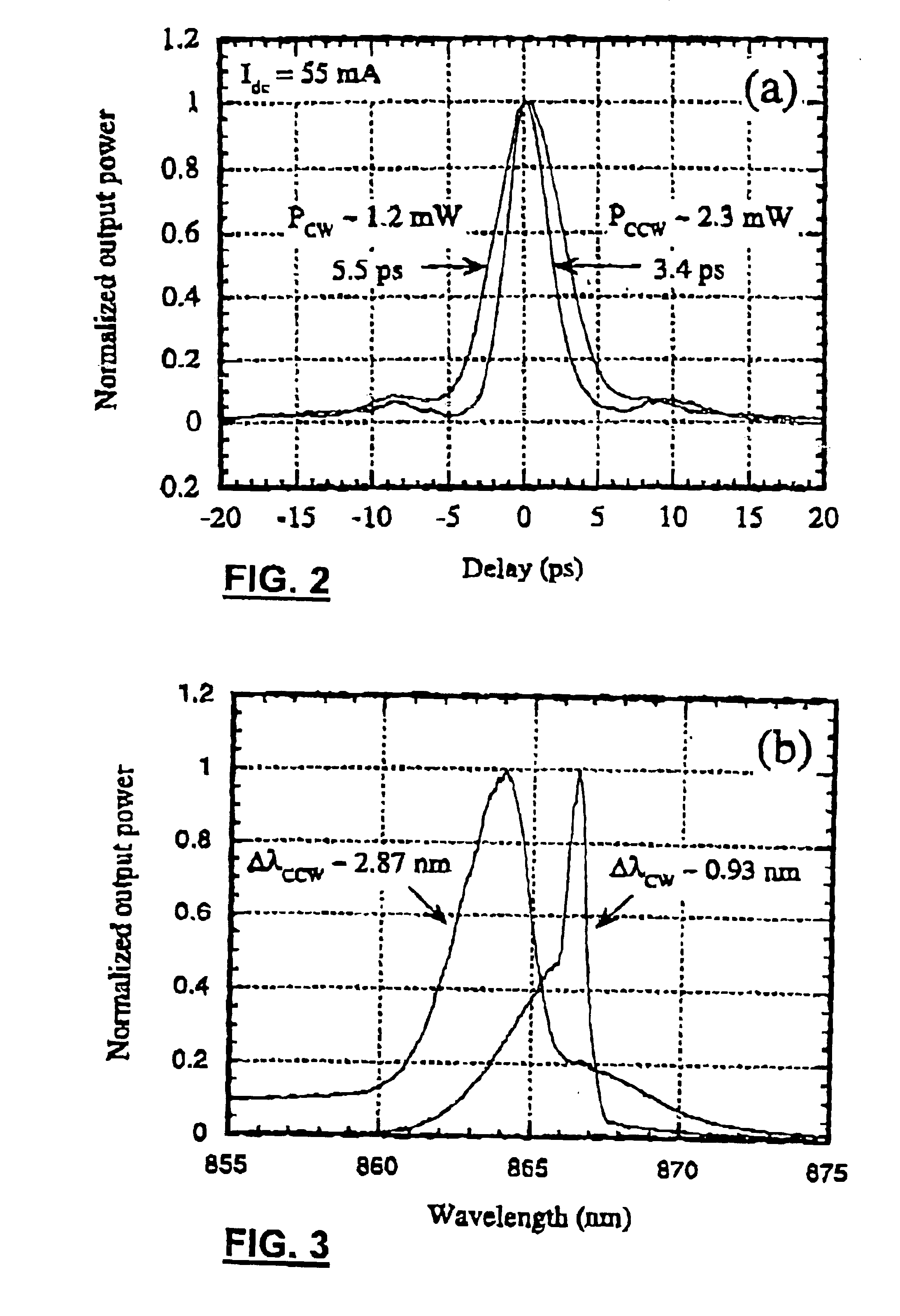
A semiconductor laser diode 10 is inserted in a ring cavity 12. The laser emission undergoes a transition from a noisy multimode operational regime to a mode-locked operational regime. In the mode-locked regime, trains of counterpropagating picosecond pulses are generated. The counterpropagating pulses are temporally synchronized and are centered about different wavelengths.

Dual-wavelength emission is a novel characteristic of a passive self-modulated mode-locked semiconductor laser diode 10. The procedure used to mode-lock the semiconductor laser diode 10 includes a proper cavity alignment as a key feature.

The apparatus is schematically represented in FIG. 1. The apparatus includes the following elements:A semiconductor laser diode amplifier 10. The laser diode amplifier provides a gain necessary for lasing action. The laser diode 10 is a superluminescent diode such as a 500 micron long double quantum well InGaAs ridge waveguide with strained InGaAlAs active layers from EG&G Optoel...


PUM


Abstract

Method of generating laser pulses using a semiconductor laser diode as a lasing amplification medium of an extended laser cavity are presented. Passive self-modulated mode-locked operation of the semiconductor laser diode is achieved by providing an above lasing threshold direct current input current to the semiconductor laser diode while the semiconductor laser diode is operational in a slightly misaligned extended laser cavity favoring the amplification of wavelengths shorter than a center wavelength of a continuous wave operational mode of the semiconductor laser diode at threshold.

Description

FIELD OF THE INVENTIONThe invention applies to mode-locked operation of lasers, and in particular to methods of operating a semiconductor laser diode in a passive self-modulated mode-locked regime.BACKGROUND OF THE INVENTIONMode-locking of semiconductor laser diodes is of interest as such sources have applications in telecommunications and in measurement systems.Mode-locking of laser signals is used to produce trains of short pulses. Mode-locking is achieved when all modes of oscillation in a laser cavity have the same phase and when the frequency difference between neighboring oscillation modes is a constant throughout the entire emission spectrum. Under these conditions the laser signal in the time domain is defined by the coherent superposition of all oscillating, phase-locked lasing modes in the laser cavity. The main characteristics of the laser signal when mode-locking is achieved are:i. Constructive interference of all oscillating lasing modes takes place over a short period ...

Claims


Application Information

Patent Timeline
Patent Type & Authority Patents(United States)
IPC IPC(8): H01S3/098H01S3/13H01S3/11H01S3/10H01S3/121H01S5/00H01S3/081H01S3/083H01S3/105H01S5/028H01S5/065H01S5/14
CPCH01S5/065H01S5/14H01S3/0816H01S3/083H01S3/105H01S3/1115H01S5/142H01S5/028H01S5/005
Inventor PICHE, MICHELLANGLOIS, PATRICK
Owner UNIV LAVAL
Why Eureka
Try Eureka