Optical pickup apparatus, recording/reproducing apparatus provided with the optical pickup apparatus, optical element, and information recording/reproducing method

a technology of optical pickup and recording/recording apparatus, which is applied in the direction of optical beam sources, lock applications, instruments, etc., can solve the problems of serious spherical aberration, and achieve the effect of improving the efficiency of using light, improving the efficiency of light use, and simple structur

Inactive Publication Date: 2005-03-22
KONICA CORP
View PDF25 Cites 84 Cited by
  • Summary
  • Abstract
  • Description
  • Claims
  • Application Information

AI Technical Summary

Benefits of technology

Further object is to make information recording and/or information reproducing to be conducted by one pickup apparatus, for each different optical information recording medium without generating serious spherical aberration and chromatic aberration even in the case of using rays of light having at least two different wavelengths and applying to different types of optical information recording media. In addition to that, another object is to provide an optical pickup apparatus having s simple structure. In particular, when using different types of optical information recording media each having a transparent substrate with a different thickness, the problem of spherical aberration becomes more serious. Further object is that one pickup apparatus can conduct recording and/or reproducing of information for different typ

Problems solved by technology

In particular, when using different types of optical information recording media each having a transp

Method used


Image

  • Optical pickup apparatus, recording/reproducing apparatus provided with the optical pickup apparatus, optical element, and information recording/reproducing method
  • Optical pickup apparatus, recording/reproducing apparatus provided with the optical pickup apparatus, optical element, and information recording/reproducing method
  • Optical pickup apparatus, recording/reproducing apparatus provided with the optical pickup apparatus, optical element, and information recording/reproducing method

Examples


first embodiment

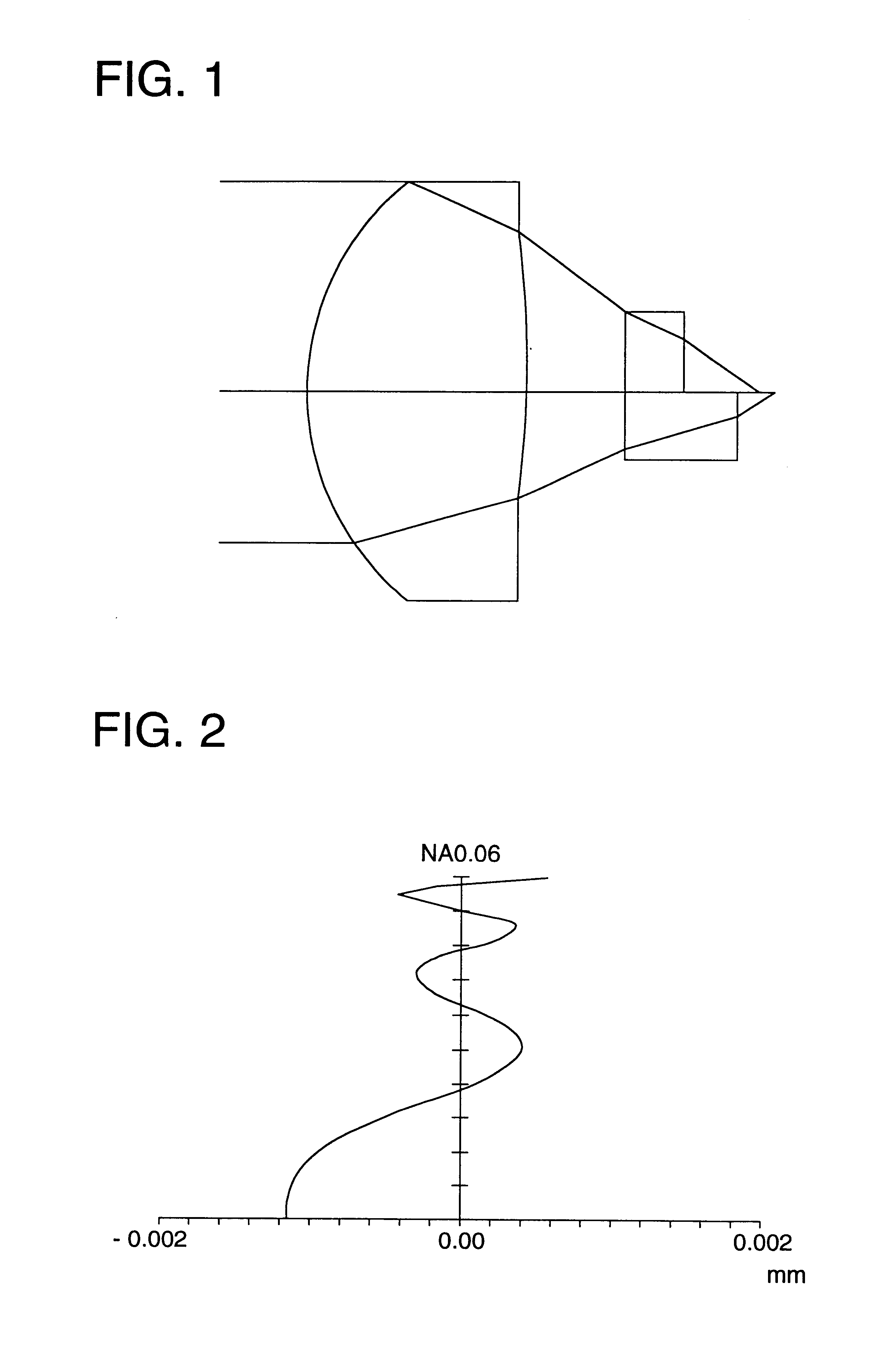
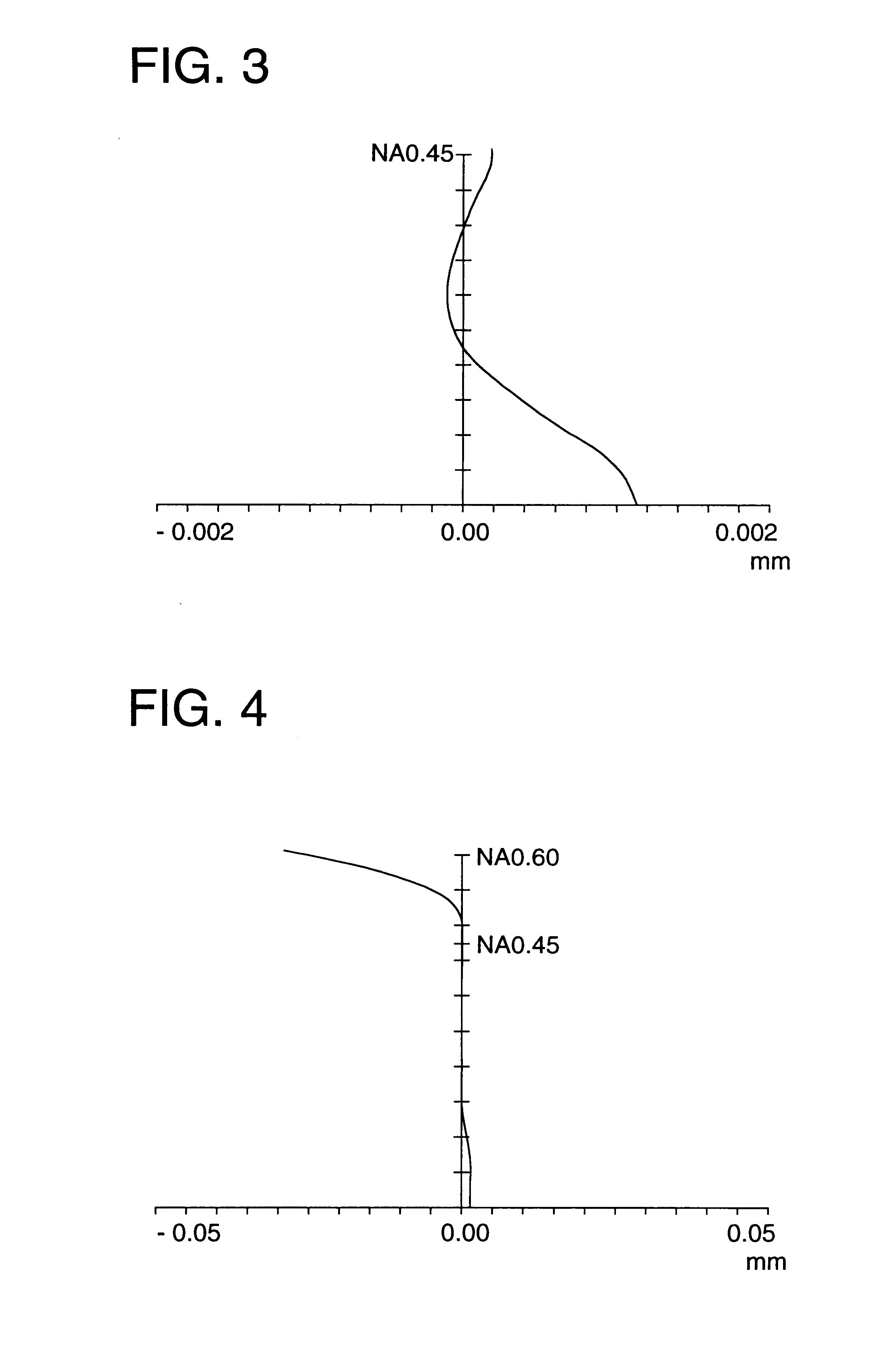
An optical system of the present invention is basically a 2-sided aspherical single lens, and diffraction annular bands (ring zonal diffraction surface) are provided on one aspherical surface. Generally, in the aspherical refractive surface, when the spherical aberration is corrected to a certain dominant wavelength light, to the wavelength light whose wavelength is shorter than that of the dominant wavelength light, the spherical aberration becomes under (insufficient correction). Reversely, in a diffraction lens which is a lens having the diffraction surface, when the spherical aberration is corrected by the dominant wavelength light, the spherical aberration can be over (excessive correction) at the wavelength which is shorter than that of the dominant wavelength light. Accordingly, when an aspherical coefficient of the aspherical surface lens by the refraction, and an coefficient of the phase difference function of the diffraction lens are properly selected and the refraction po...

second embodiment

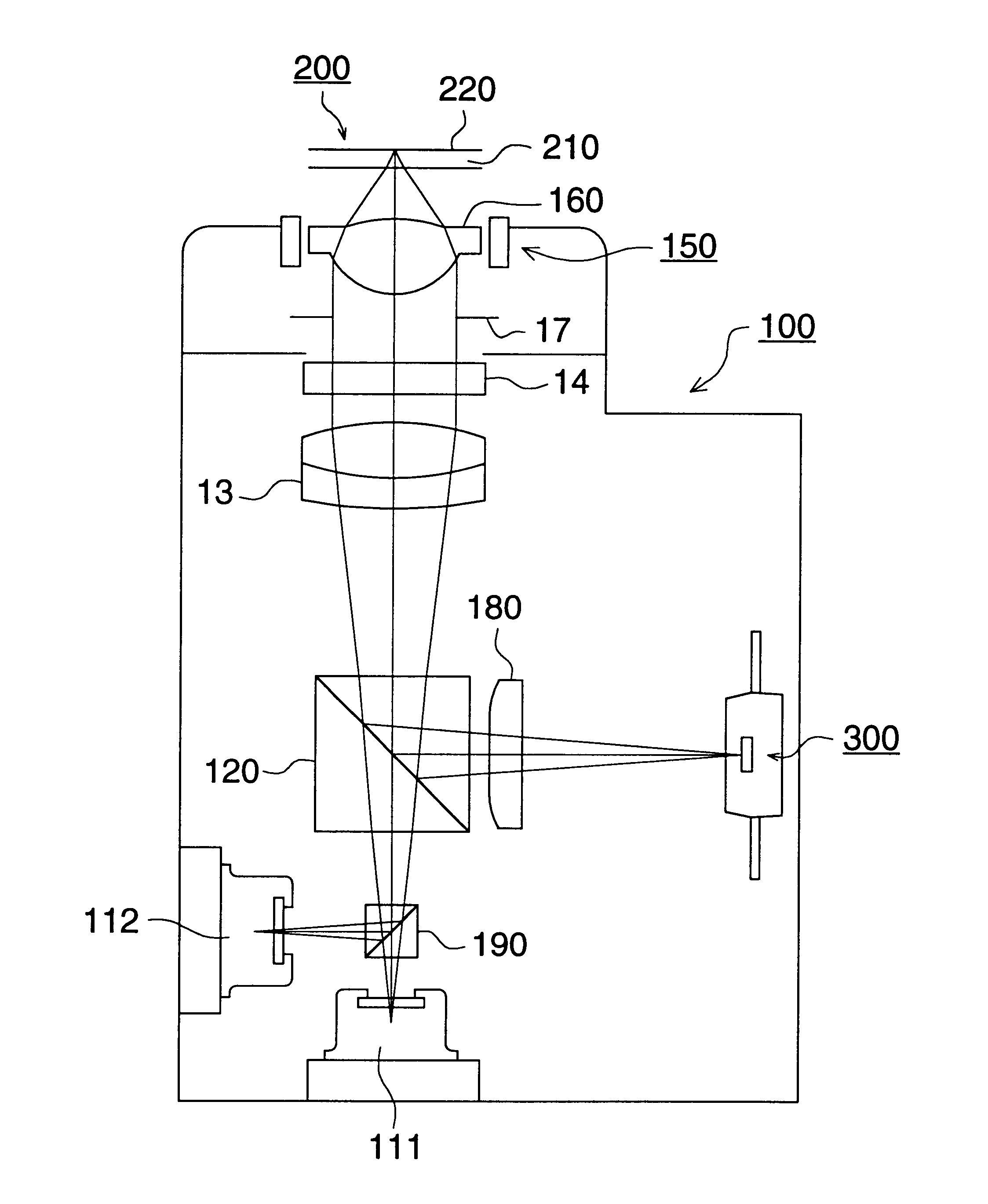
Next, the objective lens of the present invention and the structure of the optical pickup apparatus provided with the objective lens will be concretely described.

In FIG. 48, the schematic structural view of the optical pickup apparatus of the present embodiment will be shown. The optical disks 20 which are optical information recording media onto which or from which the information is recorded and / or played back by the optical pickup apparatus, are 3 types of disks which are the first optical disk (for example, a DVD) whose transparent substrate thickness is t1 and the second optical disk (for example, a blue laser use next-generation high density optical disk), and the third optical disk (for example, a CD) whose transparent substrate thickness is t2 different from t1, and hereinafter, these disks will be described as optical disks 20. Herein, the transparent substrate thickness t1=0.6 mm, and t2=1.2 mm.

The optical pickup apparatus shown in the drawing has, as the light sources, th...

third embodiment

Next, the objective lens and the structure of the optical pickup apparatus including the objective lens of the present invention, will be concretely described.

In FIG. 49, the schematic structural view of the optical pickup apparatus of the present embodiment will be shown. The optical pickup apparatus shown in FIG. 49 is an example in which the laser / detector integration unit 40 into which the laser, light detector, and hologram are structured as a unit, is used, and the same components as in FIG. 48 are shown by the same numeral codes. In this optical pickup apparatus, the first semiconductor laser 11, blue laser 12, the first light detection means 31, the second light detection means 32 and the hologram beam splitter 23 are structured into a unit as the laser / detector integration unit 40.

When the first optical disk is played back, the light flux emitted from the first semiconductor laser 11 transmits trough the hologram beam splitter 23, and is stopped down by the diaphragm 3, and...


PUM


Abstract

An optical pickup apparatus for reproducing information from an optical information recording medium or for recording information onto an optical information recording medium, is provided with a first light source for emitting first light flux having a first wavelength; a second light source for emitting second light flux having a second wavelength, the first wavelength being different from the second wavelength; a converging optical system having an optical axis and a diffractive portion, and a photo detector; wherein in case that the first light flux passes through the diffractive portion to generate at least one diffracted ray, an amount of n-th ordered diffracted ray of the first light flux is greater than that of any other ordered diffracted ray of the first light flux, and in case that the second light flux passes through the diffractive portion to generate at least one diffracted ray, an amount of n-th ordered diffracted ray of the second light flux is greater than that of any other ordered diffracted ray of the second light flux, where n stands for an integer other than zero.

Description

BACKGROUND OF THE INVENTIONThe present invention relates to an optical pickup apparatus, a recording / reproducing apparatus with the optical pickup apparatus, an optical element, and an information recording / reproducing method.Recently, as the practical application of the short wavelength red laser, a DVD which is a high density optical information recording medium (called also optical disk) having almost the same dimension as a CD (compact disk) and the larger capacity, comes into the production. In a DVD recording / reproducing apparatus, the numerical aperture NA on the optical disk side of an objective lens when a semiconductor laser of 650 nm is used, is 0.6-0.65. The DVD has a track pitch of 0.74 μm, and the minimum pit length of 0.4 μm, and is in densification, in which dimensions are lower than a half as compared to the CD having the track pitch of 1.6 μm and the minimum pit length of 0.83 μm. Further, in the DVD, in ordered to suppress the coma which is generated when the opti...

Claims


Application Information

Patent Timeline
IPC IPC(8): G11B7/125G11B7/135G11B7/00G11B7/1374G02B3/10G02B5/18G11B7/09
CPCG11B7/1275G11B7/1353G11B7/139G11B7/13922G11B7/1374G11B2007/0006E05B49/00E05B47/00E05B2047/0087
Inventor ARAI, NORIKAZUKOJIMA, TOSHIYUKIKIRIKI, TOSHIHIKOOTA, KOHEISAITO, SHINICHIRO
Owner KONICA CORP
Why Eureka
Try Eureka