Microporous diffusion apparatus

a technology of microporous diffusion and apparatus, which is applied in the direction of biological water/sewage treatment, sustainable biological treatment, borehole/well accessories, etc., can solve the problems of increasing the efficacy and speed (and resulting cost) of remediation of sites, and achieves rapid and efficient removal

Inactive Publication Date: 2005-03-29
KERFOOT TECH
View PDF26 Cites 54 Cited by
  • Summary
  • Abstract
  • Description
  • Claims
  • Application Information

AI Technical Summary

Benefits of technology

In particular the present invention is directed to sparging apparatuses for employing microporous diffusers for injecting micro-fine bubbles containing encapsulated gas bubbles into aquifer regions to encourage biodegradation of leachate plumes which contain biodegradable organics, or Criegee decomposition of leachate plumes containing dissolved chlorinated hydrocarbons. The sparging apparatuses of the present invention, employing microporous diffusers for injecting an encapsulated multi-gas oxidizing agent, are particularly useful in that the apparatuses promote extremely efficient removal of poorly biodegradable organics, particularly dissolved chlorinated solvents, without vacuum extraction of undesirable by-products of remediation and wherein remediation occurs by employing encapsulated multi-gas oxidizing agent for destroying organic and hydrocarbon material in place with without release of contaminating vapors.
Another object is to provide multi-gas systems to be used in combination with the microporous diffusers to promote an efficient removal of poorly biodegradable organics, particularly dissolved chlorinated solvents, without vacuum extraction.

Problems solved by technology

It is the insitu stripping action and maintenance of low solvent gas concentration in the bubbles which increases the efficacy and speed (and resulting cost) of remediation of a site.

Method used


Image

  • Microporous diffusion apparatus
  • Microporous diffusion apparatus
  • Microporous diffusion apparatus

Examples


Embodiment Construction

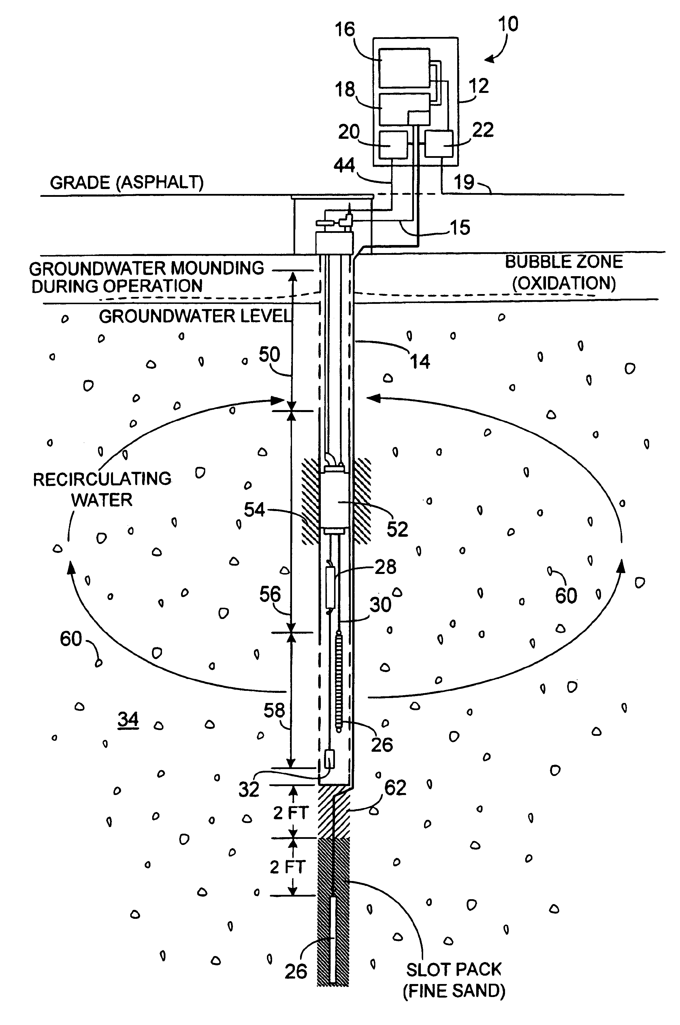
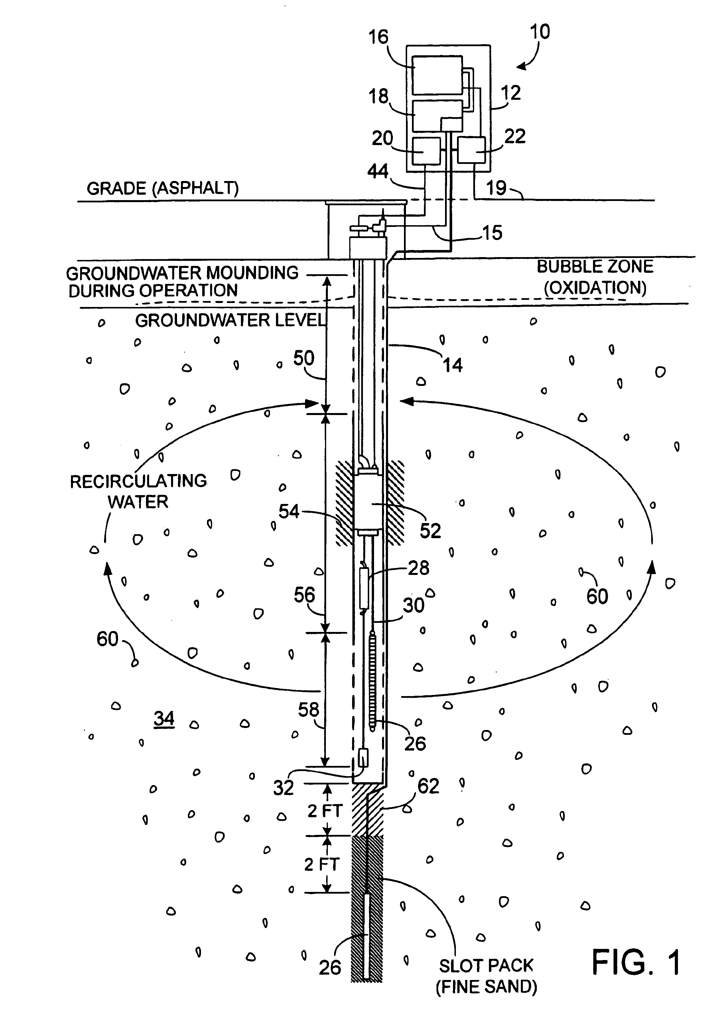
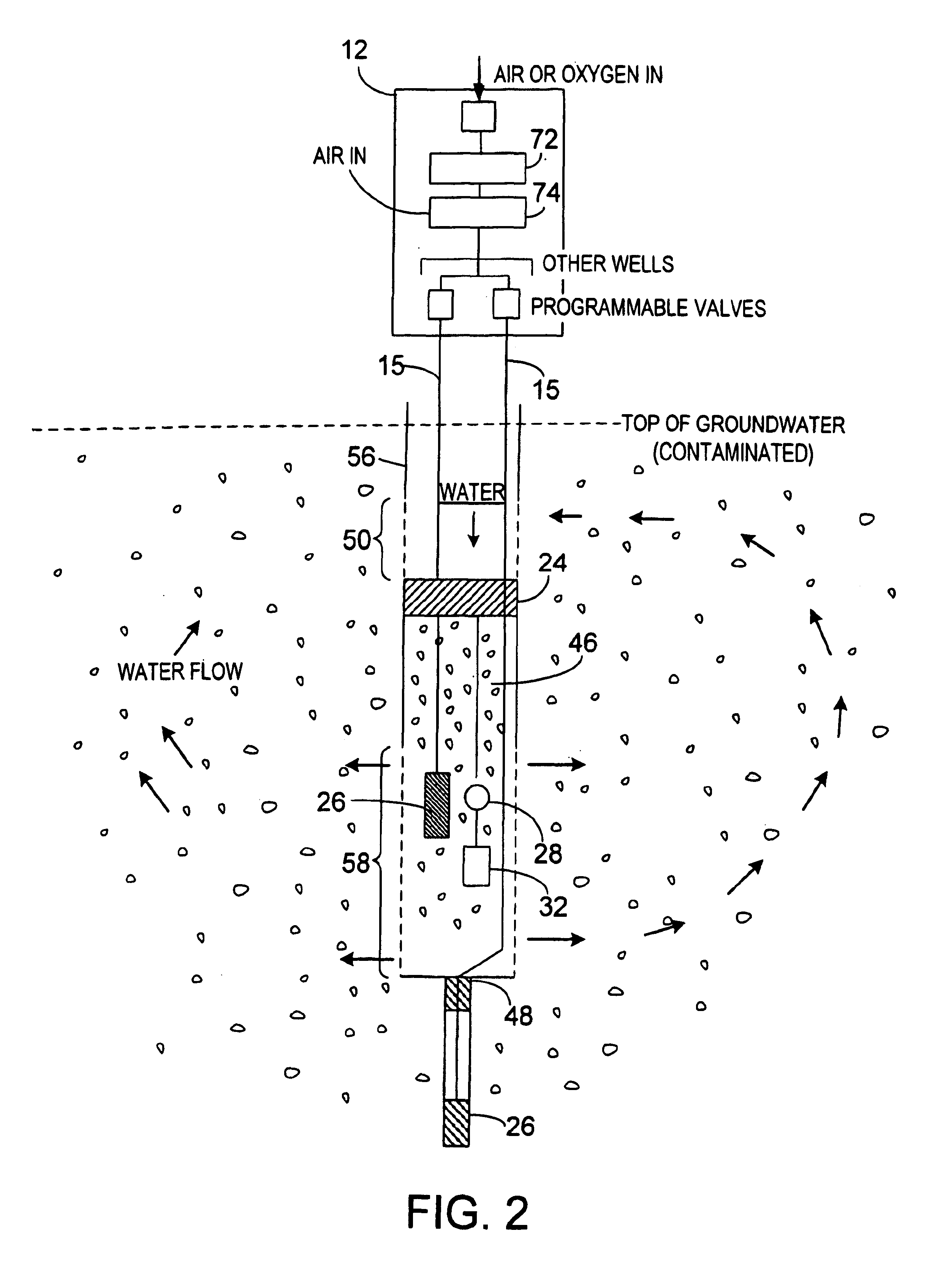
The present invention is directed to sparging apparatus for injection of oxidizing gas in the form of small bubbles into aquifer regions to encourage in situ remediation of subsurface leachate plumes. In particular the present invention employs microporous diffusers injecting multi-gas bubbles into aquifer regions to encourage biodegradation of leachate plumes which contain biodegradable organics, or Criegee decomposition of leachate plumes containing dissolved chlorinated hydrocarbons.

Referring to the FIGS. 1 through 6 there is shown a Sparge System 10 consisting of multiple microporous diffusers in combination with an encapsulated multi-gas system, the system 10 consists of a master unit 12 and one or more in-well sparging units 14. Each master unit 12 can operate up to a total of three wells simultaneously, and treating an area up an 50 feet wide and 100 feet long. Actual performance depends upon site conditions. Vapor capture is not normally necessary. In the preferred embodimen...


PUM

PropertyMeasurementUnit
sizeaaaaaaaaaa
pore sizeaaaaaaaaaa
diameteraaaaaaaaaa

Abstract

Apparatus for active in situ multi-element gas sparging for bioremediation or physico-chemical degration for removal of contaminants in a soil formation containing a subsurface groundwater aquifer or a substantially wet unsaturated zone, the multi-gas contained in bubbles, wherein the apparatus includes a plurality of injection wells extending to a depth of a selected aquifer; introducing an oxidizing agent comprising ozone mixed with ambient air to provide a multi-element gas by means of microporous diffusers, without applying a vacuum for extraction of stripped products or biodegration by-products, wherein said diffusers form micro-fine bubbles containing said multi-element gas that oxidizes, by stripping and decomposition, chlorinated hydrocarbons from the aquifer and surrounding saturated soil formation into harmless by-products; also including a pump for agitating water in the well selecting microbubbles, injecting them into the aquifer and effective to alter the path of micro-fine bubbles through a porous solid formation whereby enhanced contact between the oxidizing agent contained in each said bubble by stripping pollutant from solution in ambient water into the mini-atmosphere of each bubble effective to increase the efficiency and speed of remediation of a site.

Description

BACKGROUND OF THE INVENTION1. Field of the Invention (Technical Field)The present invention relates to apparatuses for remediation of dissolved chlorinated hydrocarbons in aquifer regions by injecting micro-fine bubbles effective for active in situ groundwater remediation for removal of dissolved chlorinated hydrocarbon solvents and dissolved hydrocarbon petroleum products. Remediation of saturation soils may also be obtained by employment of the present invention.2. Background Prior ArtThere is a well recognized need to cleanup of subsurface leachate plumes in aquifer regions and contaminated sites including in particular, dry-cleaning establishments and U.S. Military Air bases. Applicant is aware of prior art devices that have used injection of air to facilitate biodegradation of plumes.However there has not been shown apparatus for remediating a site in a controlled manner of poorly biodegradable organics, particularly dissolved chlorinated solvents with micro-fine bubbles includ...

Claims


Application Information

Patent Timeline
Patent Type & Authority Patents(United States)
IPC IPC(8): B01F3/04B09C1/10B09C1/08B09C1/00C02F3/22E21B43/00
CPCB01F3/04262B09C1/00B09C1/002B09C1/08B09C1/10C02F1/78C02F3/226E21B43/00Y10S210/908B01F2003/04858B01F2003/04886B01F2215/0052B09C2101/00C02F2103/06Y10S210/909B01F2003/04319Y02W10/10B01F23/23123B01F23/231265B01F23/2373B01F23/237613B01F2101/305
Inventor KERFOOT, WILLIAM B.
Owner KERFOOT TECH
Why Eureka
Try Eureka