Preparation of hydrogen peroxide from hydrogen and oxygen

a technology of hydrogen peroxide and hydrogen peroxide, which is applied in the field of hydrogen peroxide preparation from hydrogen and oxygen, can solve the problem of 180° deflection of the flow direction in very small observation windows, and achieve the effect of preventing the decomposition of hydrogen peroxid

Inactive Publication Date: 2005-03-29
BASF AG
View PDF6 Cites 18 Cited by
  • Summary
  • Abstract
  • Description
  • Claims
  • Application Information

AI Technical Summary

Benefits of technology

It is advantageous to pass the liquid stream through the reaction space in the direction of gravity and to introduce the gas stream via the side walls bounding the reaction space. Unreacted constituents of the gas stream are taken off at the opposite side wall after passing through the reaction space. Openings which allow passage of gas are provided in at least parts of the side walls for the introduction and discharge of gas streams. The openings can be macroscopic openings, e.g. holes or slits, or microscopic channels of a gas-permeable porous material, e.g. a sintered metal or a gas-permeable ceramic. The individual openings in the side walls can be connected to individual gas feed lines and gas discharge lines. However, it is more practical for the side walls to separate the reaction space from at least one compartment which supplies gas and at least one compartment through which gas flows out from the reactor.
The pressure in the compartment which supplies gas decreases with increasing distance from the feed point. To ensure uniform supply of gas at each point of the reaction space, the resistance offered by the side wall bounding the reaction space to the passage of gas can be decreased approximately proportionally to the decreasing gas pressure. This can be achieved, for example, by increasing the number and the area of the openings or by increasing the porosity of the dividing wall in the flow direction of the gas in the compartment which supplies gas.
The molar ratio of oxygen to hydrogen in the gas stream fed in is generally from 2:1 to 1000:1, preferably from 5:1 to 100:1, particularly preferably from 20:1 to 50:1. Apart from the reaction gases hydrogen and oxygen, the gas stream may also further comprise at least one inert gas, for example nitrogen or argon. The use of an inert gas can be advantageous in order to avoid the hitherto problematical handling of compressed gases having a high oxygen content. When an inert gas is used, the proportion of inert gas is appropriately from 50 to 80% by volume, preferably from 60 to 80% by volume and in particular from 70 to 80% by volume. Oxygen can also be used in the form of air. The proportion of hydrogen should preferably not exceed the lower explosive limit of 4% by volume at any point of the reaction. The gas stream which leaves the reaction space and has been depleted in oxygen and hydrogen is generally admixed with fresh oxygen and hydrogen and returned to the reaction space. If the gas stream comprises an inert gas, the replacement of the oxygen and hydrogen consumed in the reaction is preferably carried out using essentially pure oxygen or hydrogen so as to avoid accumulation of the inert gas in the gas stream.
The liquid stream which dissolves the hydrogen peroxide formed at the catalyst surface and transports it from the reaction space comprises water and / or a C1-C4-alkanol, preferably solely water. When the liquid stream comprises a C1-C4-alkanol, the gas stream preferably comprises an inert gas. In addition, the liquid stream advantageously further comprises stabilizers which are designed to prevent the decomposition of hydrogen peroxide.

Problems solved by technology

This can in extreme cases, depending on the particle shape, lead to deflection of the flow direction by 180° in very small observation windows.

Method used


Image

  • Preparation of hydrogen peroxide from hydrogen and oxygen
  • Preparation of hydrogen peroxide from hydrogen and oxygen
  • Preparation of hydrogen peroxide from hydrogen and oxygen

Examples


production example 1

CATALYST PRODUCTION EXAMPLE 1

5 m3 (gross volume as poured) of steatite spheres having a diameter of from 1.8 to 2.2 mm were impregnated on a box filter with a solution of 15 kg of tin(II) chloride and 30 l of hydrochloric acid in 3 m3 of water. The solution was allowed to seep through the spheres and the bed was washed with 5 m3 of water. A solution of 1000 g of palladium chloride and 5 l of concentrated hydrochloric acid in 3 m3 of water was subsequently allowed to seep through the steatite spheres, the filtrate was collected and the bed was once again rinsed with water. The procedure was repeated one more time. The spheres were then dried overnight at 50° C. and 100 mbar.

The spheres which had been activated in this way were then placed in a double-walled tube which was connected to a pump for circulating liquid. The jacket of the tube could be heated by means of hot / warm water. After addition of a solution of 273 kg of sodium hypophosphite, 616 kg of ammonium chloride and 911 l of...

production example 2

CATALYST PRODUCTION EXAMPLE 2

The catalyst was produced by a method analogous to that of example 1, but the steatite spheres used had a diameter of from 1.0 to 1.5 mm.

example 1

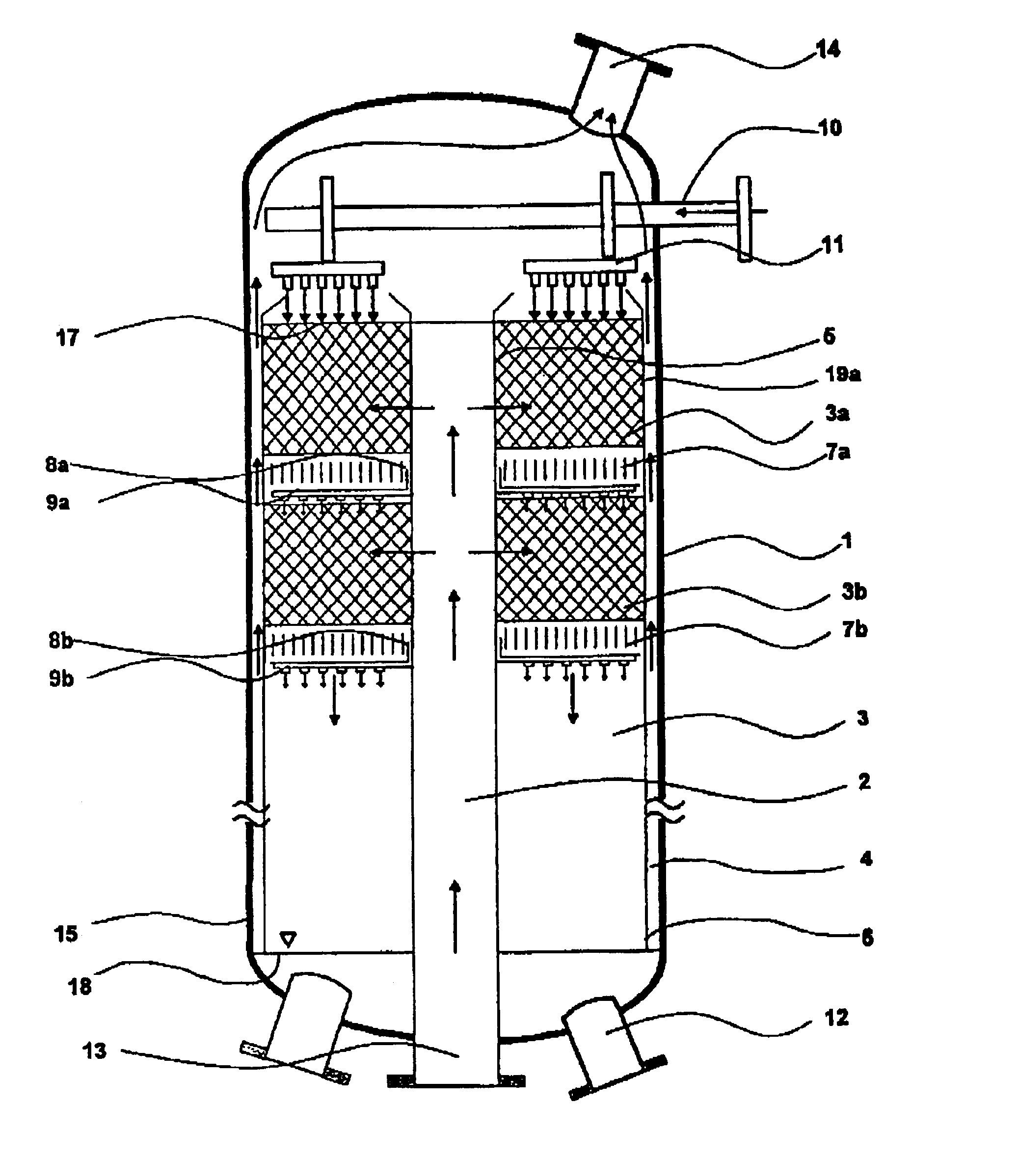
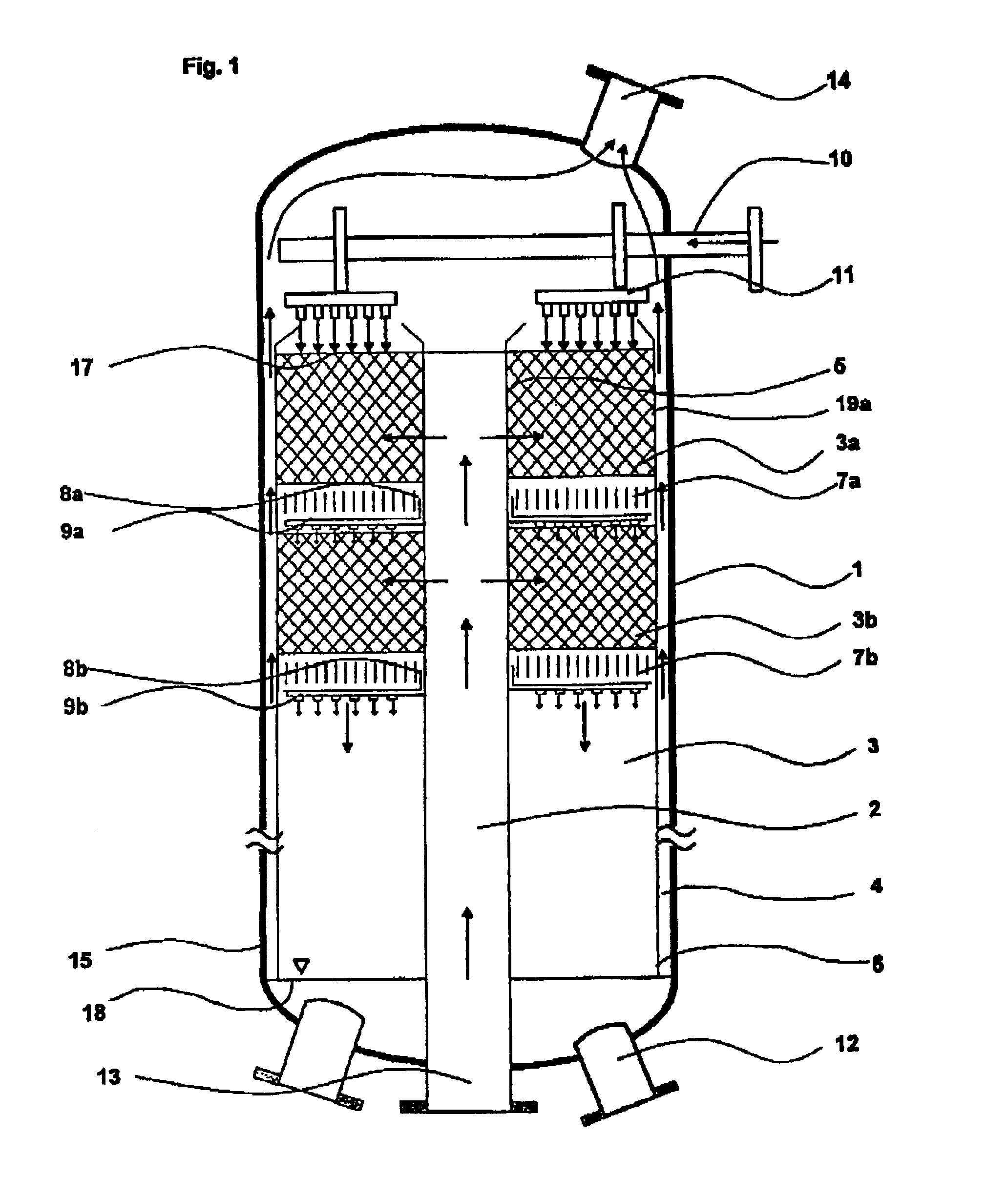
A plant as shown in FIG. 3 was used. The reactor had an external diameter of 2.6 m and a height of 23.6 m. The reaction space had an external diameter of 2.3 m, an internal diameter of 0.5 m and extended from above the bottom region (1.9 m from the lower end of the reactor) to below the top region (2.2 m from the upper end of the reactor). The catalyst volume was 49 m3. The reaction space was made up of 16 reaction zones with 15 cooling zones located between them. The reaction zones were filled with the catalyst produced as described in catalyst production example 1. A liquid stream A which had been preheated to 43° C. was introduced via a liquid distributor and distributed uniformly over the surface of the uppermost reaction zone. The liquid trickled through the uppermost reaction zone and took up the hydrogen peroxide formed over the catalyst. The liquid was held up in the first cooling zone and cooled by indirect heat exchange. After leaving the cooling zone, the liquid was distr...


PUM

PropertyMeasurementUnit
angleaaaaaaaaaa
aspect ratioaaaaaaaaaa
particle sizeaaaaaaaaaa

Abstract

In a process for preparing an aqueous and / or alcoholic solution of hydrogen peroxide by reaction of hydrogen and oxygen in a trickle-bed reactor over a supported catalyst including a noble metal, the apparent flow direction of the gas stream and the apparent flow direction of the liquid stream are not parallel to one another. The apparent flow direction of the gas stream preferably runs radially from the longitudinal axis to the circumference of the reactor. The process allows high gas throughputs with a small pressure drop.

Description

BACKGROUND OF THE INVENTION1. Field of the InventionThe present invention relates to a process for preparing an aqueous and / or alcoholic solution of hydrogen peroxide by reaction of hydrogen and oxygen over a stationary catalyst comprising a noble metal.2. Discussion of the BackgroundThe synthesis of hydrogen peroxide from hydrogen and oxygen over heterogeneous catalysts has been described many times. Thus, EP-A 0 579 109 describes the direct synthesis of hydrogen peroxide in a fixed-bed reactor operated in the downflow mode. Here, the catalyst is present as a fixed bed in the reactor. A gas stream comprising hydrogen and oxygen and a liquid aqueous stream are passed through the reactor in cocurrent from the top downward.The factor which limits the formation rate of hydrogen peroxide is, at a given catalyst activity, the amount of reaction gases present at the surface of the catalyst. One restriction imposed on this is due to the requirement that, for safety reasons, the proportion ...

Claims


Application Information

Patent Timeline
Patent Type & Authority Patents(United States)
IPC IPC(8): B01J8/04B01J23/40C01B15/00C01B15/029B01J37/00B01J37/02B01J37/03
CPCB01J8/0415B01J8/0492C01B15/029B01J23/40B01J37/0203B01J37/031
Inventor FISCHER, MARTINBUTZ, THOMASMASSONNE, KLEMENS
Owner BASF AG
Why Eureka
Try Eureka