Two-level supply voltage detection circuit
a detection circuit and supply voltage technology, applied in the field of detection circuits, can solve the problems of consuming electric current all the time, unable to ignore the current consumption of the affecting the operation of the detection circuit, so as to reduce the layout area of the entire two-level supply voltage detection circuit, reduce the layout area of the resistive element, and reduce the effect of current consumption
- Summary
- Abstract
- Description
- Claims
- Application Information
AI Technical Summary
Benefits of technology
Problems solved by technology
Method used
Image

Examples
embodiment 1
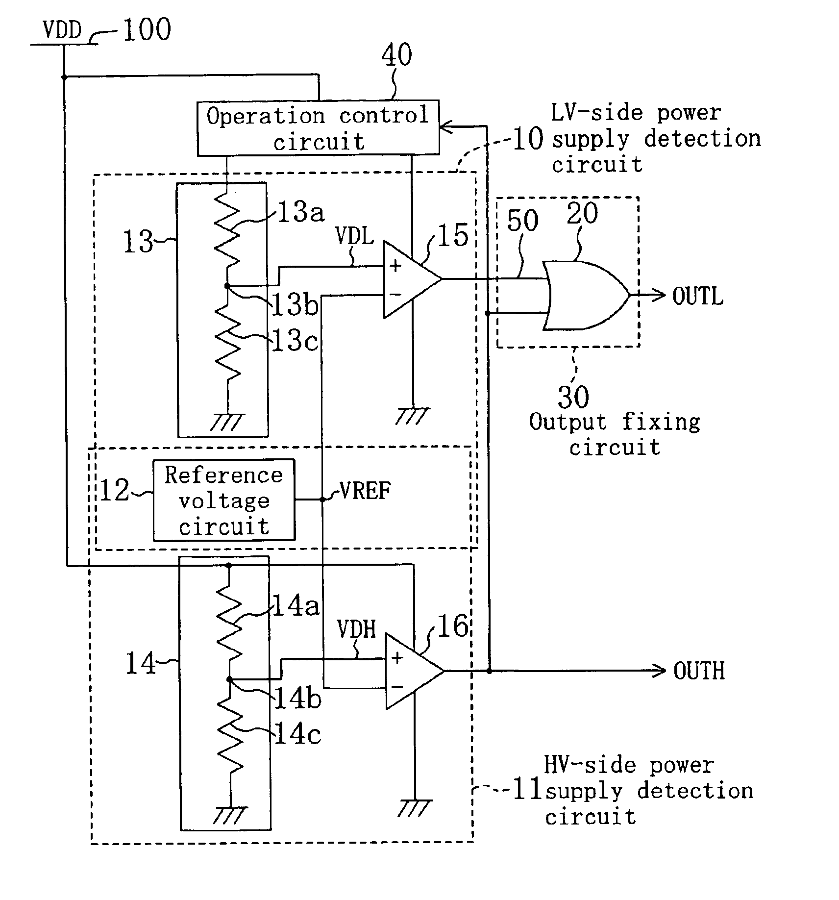
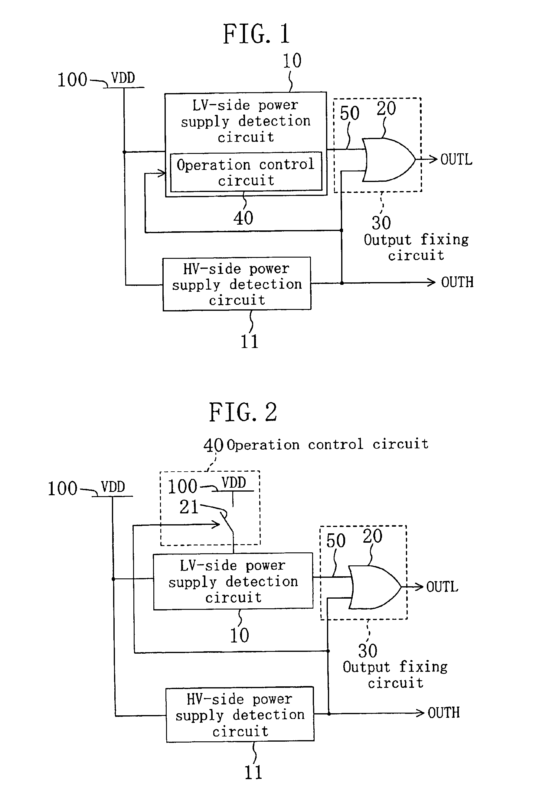
[0040]FIG. 1 is a circuit diagram of a two-level supply voltage detection circuit according to embodiment 1. In the two-level supply voltage detection circuit of FIG. 1, reference numeral 10 denotes a power supply detection circuit on the low voltage side (hereinafter, referred to as “LV-side power supply detection circuit 10”); reference numeral 11 denotes a power supply detection circuit on the high voltage side (hereinafter, referred to as “HV-side power supply detection circuit 11”); reference numeral 30 denotes an output fixing circuit (LV-side power supply detection output fixing means); reference numeral 40 denotes an operation control circuit (detection operation control means); reference numeral 50 denotes a low-voltage-side (LV-side) detection signal which is an output signal of the LV-side power supply detection circuit 10, reference numeral 100 denotes a power supply (high-voltage-side (HV-side) power supply) having voltage value VDD, reference mark OUTH denotes a high-v...
embodiment 2
[0049]Now, embodiment 2 of the present invention is described.
[0050]FIG. 2 is a circuit diagram of a two-level supply voltage detection circuit of embodiment 2. In embodiment 2, the operation control circuit 40 of embodiment 1 shown in FIG. 1 includes a switch 21 (second switch) inserted between the power supply 100 and the LV-side power supply detection circuit 10. The switch 21 receives a HV-side detection signal OUTH. When the received HV-side detection signal OUTH is inactive, the switch 21 is turned on. When the received HV-side detection signal OUTH is active, the switch 21 is turned off. It should be noted that, in embodiments 2 to 11, elements having the same functions are denoted by the same reference numerals used in embodiment 1, and descriptions thereof are herein omitted.
[0051]The operation of the two-level supply voltage detection circuit of embodiment 2 is described. Herein also, the description is given for each of the cases sorted according to the relationship betwe...
embodiment 3
[0054]Now, embodiment 3 of the present invention is described.
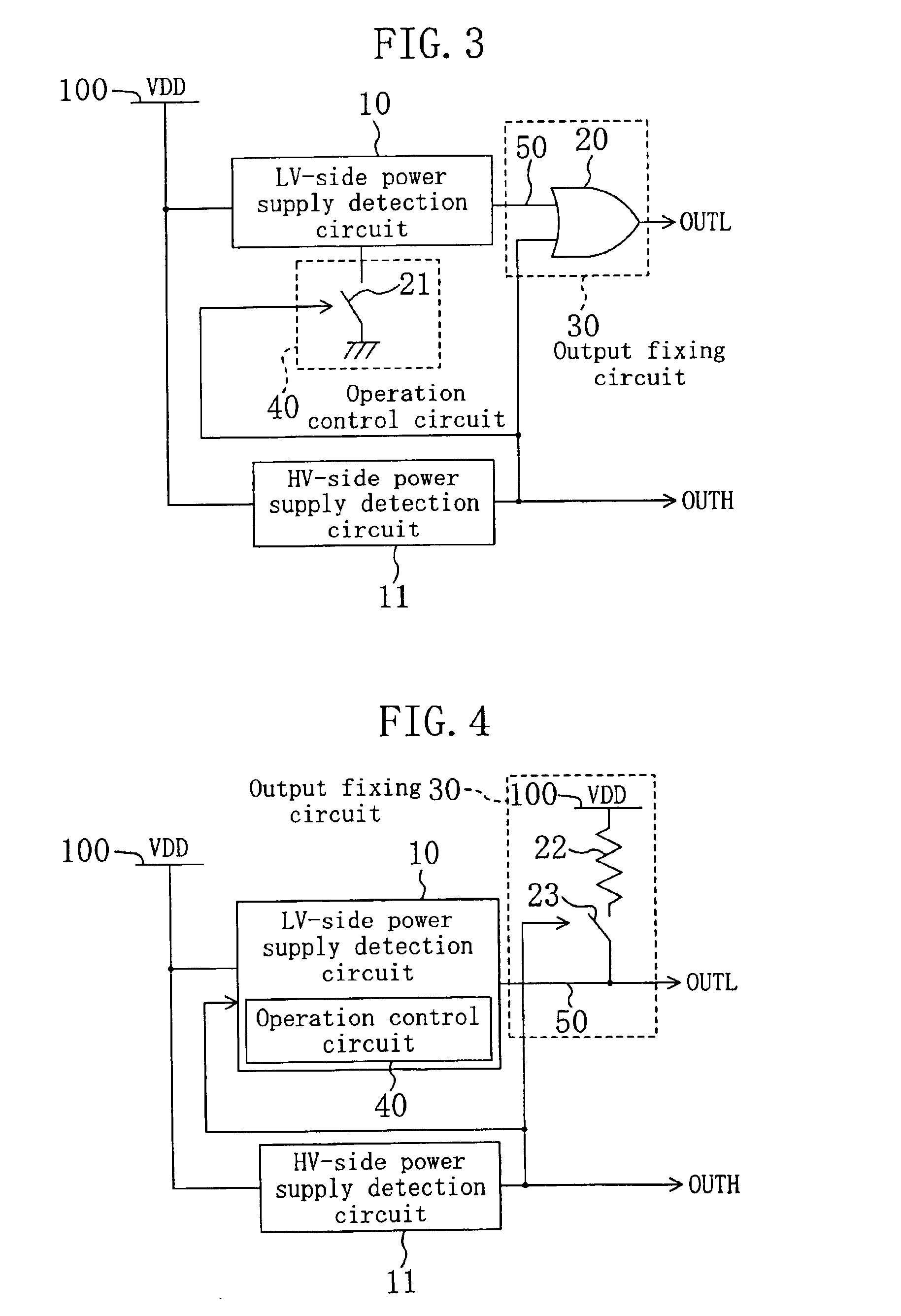
[0055]FIG. 3 is a circuit diagram of a two-level supply voltage detection circuit of embodiment 3. In embodiment 3, the operation control circuit 40 of embodiment 1 shown in FIG. 1 includes a switch 21 inserted between a ground terminal of the LV-side power supply detection circuit 10 and a ground power supply (lower-voltage-side power supply). As described in embodiment 2, the switch 21 receives a HV-side detection signal OUTH and is turned on only when the received HV-side detection signal OUTH is inactive.
[0056]The operation of the two-level supply voltage detection circuit of embodiment 3 is described. Herein also, the description is given for each of the cases sorted according to the relationship between voltage value VDD of the power supply 100 and HV-side reference value VREFH.
[0057]In the first place, a case where voltage value VDD of the power supply 100 is lower than HV-side reference value VREFH is described. I...
PUM
 Abstract
Description
Claims
Application Information
 - R&D
- Intellectual Property
- Life Sciences
- Materials
- Tech Scout
- Unparalleled Data Quality
- Higher Quality Content
- 60% Fewer Hallucinations
Browse by: Latest US Patents, China's latest patents, Technical Efficacy Thesaurus, Application Domain, Technology Topic, Popular Technical Reports.
© 2025 PatSnap. All rights reserved.Legal|Privacy policy|Modern Slavery Act Transparency Statement|Sitemap|About US| Contact US: help@patsnap.com