
Membrane electrode assembly for polymer electrolyte fuel cell

a fuel cell and membrane electrode technology, applied in the direction of cell components, basic electric elements, electrochemical generators, etc., can solve the problems of insufficient deterioration of generation efficiency, reduced water-discharging ability of membrane electrode assemblies, carbon particle corrosion, etc., to achieve stable existence, maintain carbon monoxide poisoning resistance, reduce the effect of ru leaching

Inactive Publication Date: 2005-04-05
HONDA MOTOR CO LTD
View PDF5 Cites 71 Cited by
  • Summary
  • Abstract
  • Description
  • Claims
  • Application Information

AI Technical Summary

Benefits of technology

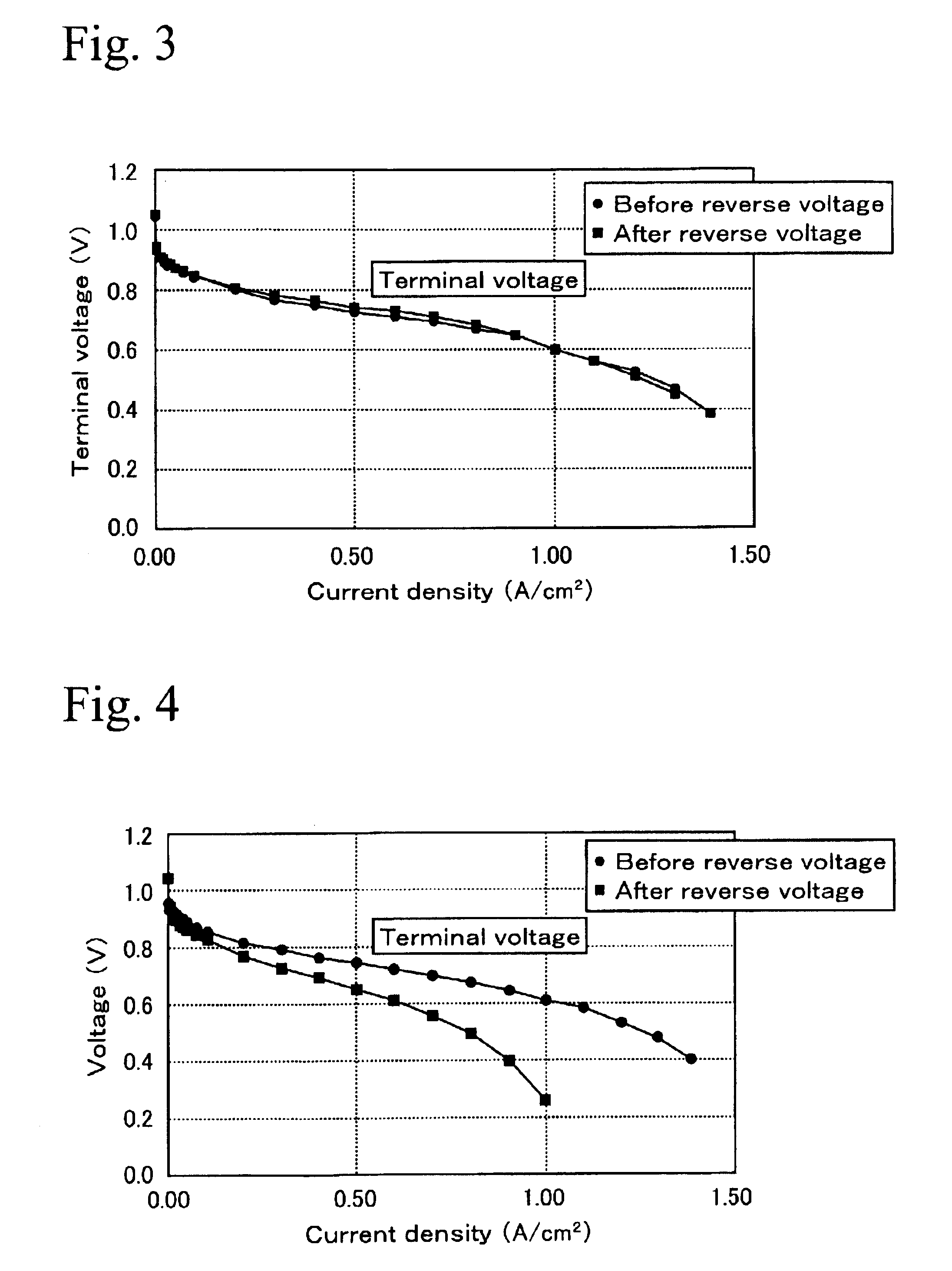
Therefore, an object of the present invention is to provide a polymer electrolyte fuel cell and a membrane electrode assembly for the polymer electrolyte fuel cell which can exhibit almost the same generation efficiency as that before occurrence of reverse voltage, even after the occurrence of the reverse voltage.
However, by further research by the inventors, it was confirmed that leaching of Ru occurs in the Ru-rich hexagonal closest packed structure accompanied with the occurring of reverse voltage. Therefore, deterioration of generating efficiency can be restrained by using a Pt—Ru alloy which is mainly composed of Pt-rich face-centered cubic structure.
It is desirable that the Pt—Ru alloy be obtained by quenching or furnace cooling from a temperature of 1000 to 2000° C. This is because the single phase of the face-centered cubic structure is easily generated even if the added amount of Ru is increased to improve carbon monoxide poisoning resistance.
The present invention was achieved by the observation of the inference described above. That is to say, in the present invention, because the Pt—Ru alloy is contained in the anode and the crystal of Pt—Ru alloy is mainly a face-centered cubic structure, Ru can exist more stably than in hexagonal closest packed structure, and even if reverse voltage occurs, leaching out of Ru can be reduced, and as a result, the carbon monoxide poisoning resistance can be maintained and deterioration of the terminal voltage can be reduced.
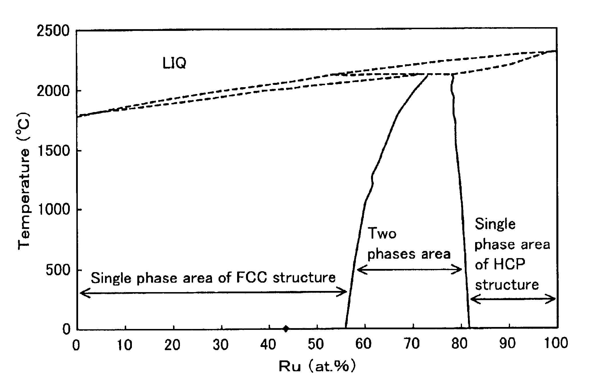
FIG. 8 is an equilibrium diagram of Pt—Ru. As shown in this diagram, it is necessary to reduce the amount of Ru in the Pt—Ru alloy to form a face-centered cubic structure. However, this results in reducing carbon monoxide poisoning resistance. Therefore, the Pt—Ru alloy which is indicated in the two-phase area of FIG. 8 in which the face-centered cubic structure and hexagonal closest packed structure coexist, was used so far. Also in the present invention, it is desirable that the atomic ratio of Ru to Pt in the Pt—Ru alloy be 28:72 to 45:55 to improve the carbon monoxide poisoning resistance.

Problems solved by technology

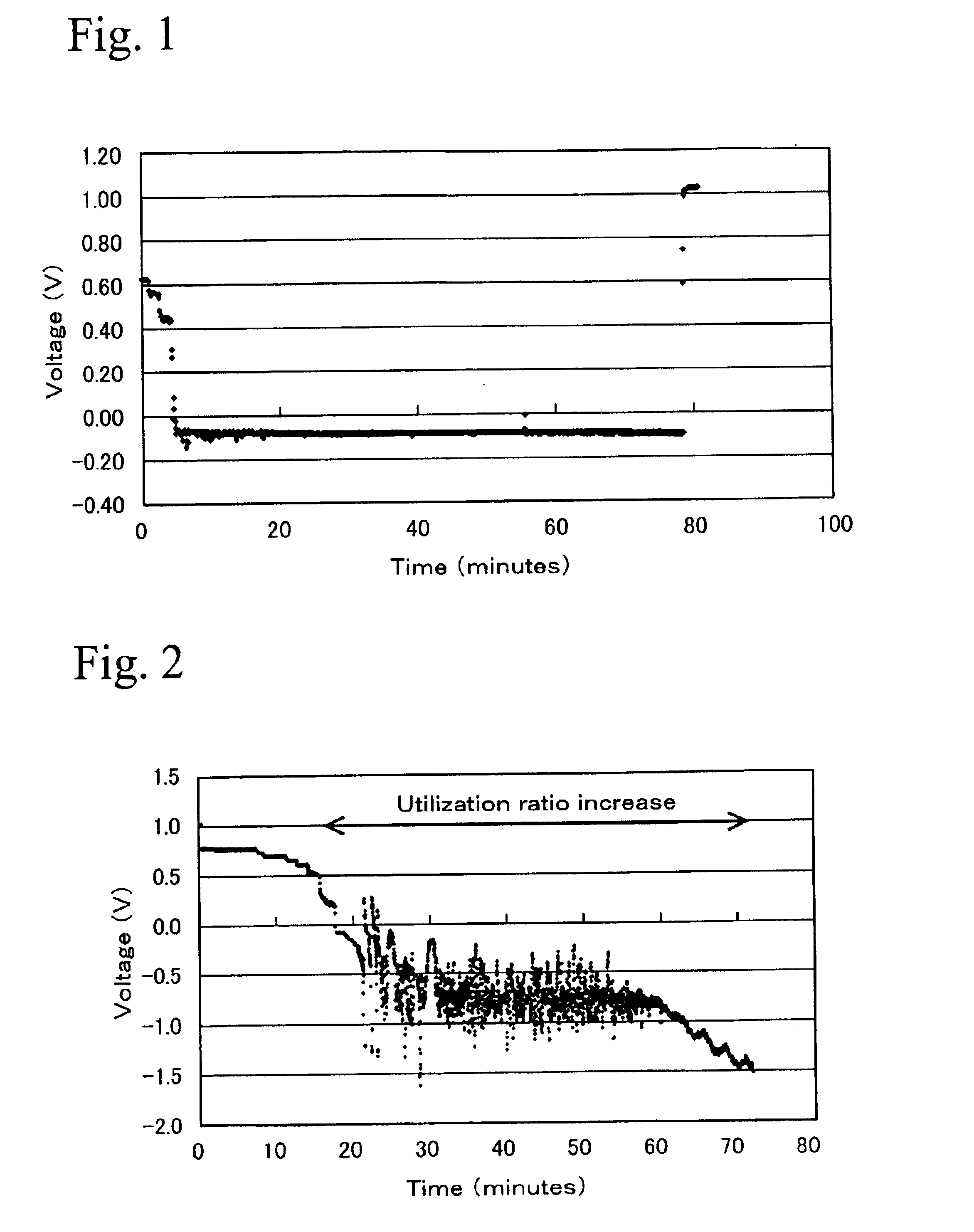
In a situation in which such a fuel cell is operated, it is known that there may be a temporary shortage of fuel gas, thereby generating reverse voltage in the entirety or a part of the anode due to the delay of fuel gas supply when the output changes extremely, or water-discharging ability of the membrane electrode assembly is reduced.
If the reverse voltage is generated, electrolysis of water is promoted, and further more, it is known that carbon particles are corroded.
However, the deterioration of generation efficiency cannot be prevented sufficiently by these methods.

Method used


Image

  • Membrane electrode assembly for polymer electrolyte fuel cell
  • Membrane electrode assembly for polymer electrolyte fuel cell
  • Membrane electrode assembly for polymer electrolyte fuel cell

Examples


Embodiment Construction

Next, the present invention is explained in detail by showing examples.

1. Preparation of Membrane Electrode Assembly

After 4500 g of dinitrodiamine platinum nitric acid solution (containing 1.5% of platinum) and 100 g of carbon blacks (Ketienblack EC) were mixed together, and platinum was carried by the carbon blacks by adding ethanol as a reducing agent.

Next, after 35.96 g of ruthenium chloride solution (containing 8.232% of ruthenium) and 710 ml of water were mixed together, 9.5 g of the carbon blacks carrying platinum described above was added, and ruthenium was also carried by the carbon black by adding ethanol. The ratio of platinum and ruthenium can be controlled by changing the amount of ruthenium in ruthenium chloride solution or the amount of mixed solution. The ratio of Pt:Ru in this example was processed to 40:60. The carbon blacks carrying Pt and Ru in the ratio of 40:60 was maintained at 1200° C. for 6 hours in an atmosphere of nitrogen gas, and cooled rapidly to process...


PUM

PropertyMeasurementUnit
temperatureaaaaaaaaaa
terminal voltageaaaaaaaaaa
voltageaaaaaaaaaa

Abstract

A membrane electrode assembly for polymer electrolyte fuel cells comprises a cathode electrode, an anode electrode, and a polymer electrolyte membrane placed between these electrodes, and a catalyst material of Pt—Ru alloy is contained in the anode and the crystal of Pt—Ru alloy is mainly of a face-centered cubic structure.

Description

BACKGROUND OF THE INVENTION1. Technical FieldThe present invention relates to a membrane electrode assembly for polymer electrolyte fuel cells, and in particular, relates to a technology which can restrain leaching of a catalyst material when there is a shortage of fuel gas, such as hydrogen, in the anode side.2. Background ArtA polymer electrolyte fuel cell (hereinafter simply referred to as “fuel cell”) is composed by laminating separators at both sides of a flat electrode structure. The electrode structure is a stacked element having a polymer electrolyte membrane held between a positive side electrode catalyst layer and a negative side electrode catalyst layer, with a gas diffusion layer laminated outside of each electrode catalytic layer. In such a fuel cell, for example, when hydrogen gas is supplied in a gas passage of the separator disposed at the negative electrode side, and an oxidizing gas is supplied in a gas passage of the separator disposed at the positive electrode si...

Claims


Application Information

Patent Timeline
Patent Type & Authority Patents(United States)
IPC IPC(8): H01M4/90H01M4/92H01M8/10H01M4/86H01M4/88
CPCH01M4/8885H01M4/926H01M4/921H01M4/8814H01M4/8828Y02E60/50H01M8/1004H01M2004/8684
Inventor TANI, MASAKIFUKUDA, KAORUIWASAWA, CHIKARAINAI, SHIGERU
Owner HONDA MOTOR CO LTD
Learn More