Heating device, heat treatment apparatus having the heating device and method for controlling heat treatment

Inactive Publication Date: 2005-04-05
TOKYO ELECTRON LTD
View PDF10 Cites 32 Cited by
  • Summary
  • Abstract
  • Description
  • Claims
  • Application Information

AI Technical Summary

Benefits of technology

In the method according to the present invention, the producing step may produce the first illuminance distribution characteristic so that the minimum is equal to or less than 0.17 W/mm2. The inventors found that the control of outputs of the double-end lamps corresponding to the first illuminance distribution characteristic does not influence a temperature of parts of the object to be processed other than the connection part. That is the connection part can be heated while an influence of simultaneous heating of other parts is negligible.
Additionally, in the method according to the present invention, the producing step may further produce a second illuminance distribution characteristic having a maximum on the object to be processed and a minimum at a part of the object to be processed above the support member, and the controlling step controls the outputs of the double-end lamps corresponding to the second illuminance distr

Problems solved by technology

However, if the reflector 4 having an inclination angle of 45 degrees is provided around each of a plurality of lamps 2, the lamps cannot be arranged closed to each other, which causes a decrease in the power density.
Although the temperature measuring device can be constituted by a thermocouple, there is a possibility that the processed body is polluted with the metal which constitutes the thermocouple since it is necessary to bring the thermocouple into contact with the object to be processed.
On the other hand, the infrared ray irradiated from the halogen lamps is absorbed by the object to be processed, thereby, raising the temperature of the object to be processed.
However, although the support ring, on which an object to be processed (foe example, a silicon substrate) is placed, is formed of ceramics (for example, SiC) having excellent heat resistance, there is a difference in temperature rise of both parts due to a difference in heat capacity.
In other words, in order

Method used


Image

  • Heating device, heat treatment apparatus having the heating device and method for controlling heat treatment
  • Heating device, heat treatment apparatus having the heating device and method for controlling heat treatment
  • Heating device, heat treatment apparatus having the heating device and method for controlling heat treatment

Examples


Embodiment Construction

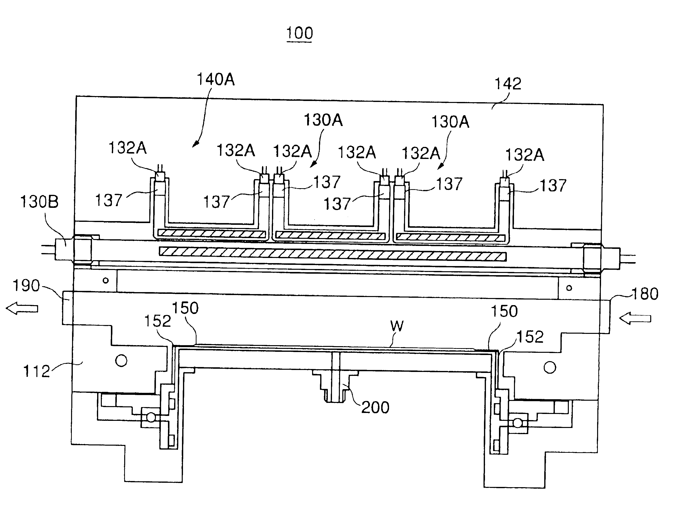
A description will now be given of a first embodiment of the present invention. FIG. 4 is a cross-sectional view of a heat treatment apparatus 100 according to the first embodiment of the present invention. FIG. 5 is a cross-sectional view of the heat treatment apparatus taken along a line V—V of FIG. 4. As shown in FIG. 4, the heat treatment apparatus 100 generally comprises a process chamber 110, a quartz window 120, a heating unit 140, a support ring 150, a gas introducing part 180, an exhausting part 190, a radiation thermometer 200 and a control part 300.

The process chamber 110 is formed of, for example, stainless steel or aluminum, and is connected to the quartz window 120. The sidewall of the process chamber 110 and the quartz window 12 define a process space in which an object W to be processed (semiconductor wafer: hereinafter referred to as a wafer W) is subjected to a heat treatment. The support ring 150 on which the wafer W is placed and a support part 152 connected to t...


PUM

PropertyMeasurementUnit
Temperatureaaaaaaaaaa
Distributionaaaaaaaaaa

Abstract

A heat treatment apparatus achieves a uniform and rapid temperature rise of an object to be processed. A plurality of double-end lamps heat the object to be processed so as to apply a heat treatment process to the object. A plurality of reflectors reflect radiation heat of the double-end lamps toward the object to be processed. Each of the double-end lamps includes a rectilinear light-emitting part and at least two double-end lamps among the plurality of double-end lamps are arranged along a longitudinal direction of the light-emitting part, or each of the double-end lamps includes a rectilinear light-emitting part and the plurality of double-end lamps are arranged so that the light-emitting parts are parallel to each other and positioned in at least two stages.

Description

TECHNICAL FIELDThe present invention generally relates to a heating device, a heat treatment apparatuses having the heating device and a heat treatment controlling method for applying a heating process to an object to be processed such as a single crystal substrate or a glass substrate. The present invention is suitable for a rapid thermal processing (RTP: Rapid Thermal Processing) used for manufacturing semiconductor devices, such as a memory or an integrated circuit (IC). The rapid thermal processing (RTP) includes rapid thermal annealing (RTA), rapid thermal cleaning (RTC), rapid thermal chemical vapor deposition (RTCVD), rapid thermal oxidization (RTO) and rapid thermal nitriding (RTN).BACKGROUND ARTGenerally, in order to manufacture a semiconductor integrated circuit, various kinds of heat treatment, such as a film deposition process, an anneal process, an oxidization diffusion process, a sputtering process, an etching process and a nitriding process may be repeatedly performed...

Claims


Application Information

Patent Timeline
IPC IPC(8): H01L21/00H01L21/205H01L21/26H01L21/31
CPCH01L21/67115
Inventor SHIGEOKA, TAKASHISAKUMA, TAKESHI
Owner TOKYO ELECTRON LTD
Why Eureka
Try Eureka