Method for removing acidic gases from waste gas

a technology of waste gas and acidic gases, applied in the direction of alkali metal sulfides/polysulfides, separation processes, sulfur compounds, etc., can solve the problems of smog and human discomfort and disability, the problem of no/sub>x is even more difficult to overcome, and the process is not suitable for the removal of nitrogen oxides

Inactive Publication Date: 2005-04-19
LEXTRAN
View PDF10 Cites 28 Cited by
  • Summary
  • Abstract
  • Description
  • Claims
  • Application Information

AI Technical Summary

Benefits of technology

[0024]According to the present invention, contacting the waste gas with the scrubbing agent can be conducted in a tower embedded with inert particles, wherein the waste gas is passed upward through the tower and the emulsion is circulated downward in a rate wh...

Problems solved by technology

These gases are the major cause for acid rain, for smog and for human discomfort and disability.
Therefore, the problem of NOx is even more difficult to overcome as it is a problem inherent to these processes and its generation cannot be avoided.
These processes however are not suitable for the removal of nitrogen oxides.
These methods are effective only within a narrow flue gas temperature range, are relatively high cost and involve the risk of ammonia leakage to the atmosphere.
In the presence of catalyst the process is more efficie...

Method used


Image

  • Method for removing acidic gases from waste gas
  • Method for removing acidic gases from waste gas
  • Method for removing acidic gases from waste gas

Examples


example 1

[0061]A glass column of 400 mm height and 30 mm diameter was heated by an outer electric heater to 80° C. The glass column was filled with glass rings of 4 mm height and 4 mm diameter and with 100 g emulsion of water in diesel derived sulfoxides comprising of 30 g water in 70 g sulfoxides. A stream of air containing 1.9% (mass percent) NO2 was bubbled continuously through the bottom of the column at a rate of 0.29 l / min for 42 hours continuously. About 75-90% of NO2 was consumed.

[0062]After 42 hours, the liquid in the column was collected and separated into two phases. The concentration of nitric acid in the aqueous phase was 20.3 wt. %.

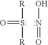
[0063]The amount of nitrous and nitric acid in the sulfoxide phase was determined by potentiometric titration in non-water medium and was found to be 21% of the total acid. In order to destroy the nitrous acid—sulfoxide complex, water were added to the organic phase and oxygen was bubbled into the liquid in order to oxidize all nitrous acid molecules...

example 2

[0066]SO2 absorption was conducted under the same conditions as in Experiment 1. SO2 concentration in the input gas was 2000 ppm. The process was carried out for 42 hours during which more than 90% of SO2 were absorbed without observing loss of absorption capability. The aqueous phase obtained at the end of the process contained only sulfuric acid. No sulfite ions (SO3) were detected.

example 3

[0067]NO2 and SO2 absorbtion was conducted simultaneously with the same reactor and emulsion composition as in Example 1 but at temperature of 20-25° C.

[0068]The concentration of NO2 was 1000 ppm and that of SO2 800 ppm.

[0069]The process was carried out the for 8 hours continuously and during this time no reduction in the absorption capability of the scrubbing agent was observed. The average concentrations of NO2 and SO2 at the output were less <10 ppm and <2 ppm respectively.

[0070]The aqueous phase obtained after collecting and separating the emulsion contained a mixture of nitric and sulfuric acids.


PUM

PropertyMeasurementUnit
Fractionaaaaaaaaaa
Weight ratioaaaaaaaaaa
Acidityaaaaaaaaaa

Abstract

A method for removing acidic gases from waste gases is disclosed. The invention relates to a method for removing acid gases, in particular from SO2 and NOx, by contacting the waste gas with an emulsion of water in organic sulfoxides, in particular of water in oil-derived-sulfoxides. The organic sulfoxide phase can be regenerated after the emulsion is loaded with polluants, by letting the emulsion to settle down and separate into two phases. The aqueous phase obtained after the separation contains sulfate and nitrate ions which can be collected and used as valuable chemicals.

Description

FIELD OF THE INVENTION[0001]The present invention relates to a method for removing acidic gases from waste gases. More specifically the present invention relates to a method for removing acid gases, in particular from SO2 and NOx, by contacting the waste gas with an emulsion of water in organic sulfoxides, in particular of water in oil-derived-sulfoxides. The organic sulfoxide phase can be regenerated after the emulsion is loaded with pollutants, by letting the emulsion to settle down and separate into two phases. The aqueous phase obtained after the separation contains sulfate and nitrate ions which can be collected and used as valuable chemicals.BACKGROUND[0002]Industrially developed countries generate billions of tons of air pollutants, a great part accounts to the combustion of coal, oil, and gasoline in electric power plants. Other major air pollution sources include petroleum refineries, cement plants and petrochemical plants.[0003]Among the most troublesome air pollutants emi...

Claims


Application Information

Patent Timeline
IPC IPC(8): B01D53/60B01D53/14
CPCB01D53/1456B01D53/60B01D53/1493Y02A50/20
Inventor KHITRIK, ADOLFPIPKO, GREGORIDORON, BENJAMIN
Owner LEXTRAN
Why Eureka
Try Eureka