Spiral wound element with improved feed space

Inactive Publication Date: 2005-04-19
FILMTEC CORPORATION
View PDF33 Cites 164 Cited by
  • Summary
  • Abstract
  • Description
  • Claims
  • Application Information

AI Technical Summary

Benefits of technology

[0032]In another embodiment of this invention, the feed spacer in the spiral wound element is characterized by both a small hydrodynamic angle (<70°) and a large strand thinning parameter (>1.3). More preferably, the hydrodynamic angle is less than 60° and the strand thinning parameter is greater than 1.35. Even more preferable, the hydrodynamic angle is less than 55

Problems solved by technology

However, increasing envelope length (as measured in the direction perpendicular from the axis of collection tube) results in greater pressure drop within the longer permeate carrier sheets and this can also decrease element flow during operation.
While such systems may achieve high recovery with high cross flow, they are also characterized by a long continuous feed path and high pressure drop.
System design can be further complicated by incorporating a variety of other options, including booster pumps, permeate pressurization, and cascading stages.
In a series of elements such as in a vessel, the first element in series operates with higher net-driving-pressure than those at the downstream end resulting in an uneven distribution of flux.
One cause for the difference is the fact that feed concentration increases in successive elements resulting in more osmotic pressure.
There are several problems with this inhomogeneous utilization of membrane.
For the lead elements, high flux can substantially shorten the life of an element due to fouling and scaling.
High flux also promotes concentration polarization and polarization decreases the effective rejection of the membrane.
Lower flux in the trailing elements is also undesirable, not only because of decreased productivity, but also because lower flux means higher solute concentration in the permeate.
Pressure drop can result in a need for higher overall pressure requiring greater energy input and necessitating higher cost equipment (pumps, piping, vessels, etc.).
In any case, these remedial measures result in greater complexity and cost.
Unfortunately, the selection of an optimal feed spacer sheet can be a complex task as several key aspects of the feed spacer sheet are difficult to predict from its structure.
For instance, increasing a spacer's thickn

Method used


Image

  • Spiral wound element with improved feed space
  • Spiral wound element with improved feed space
  • Spiral wound element with improved feed space

Examples


examples

[0061]While not intending to limit the scope of invention, the present invention is further illustrated by the following non-limiting examples:

example i

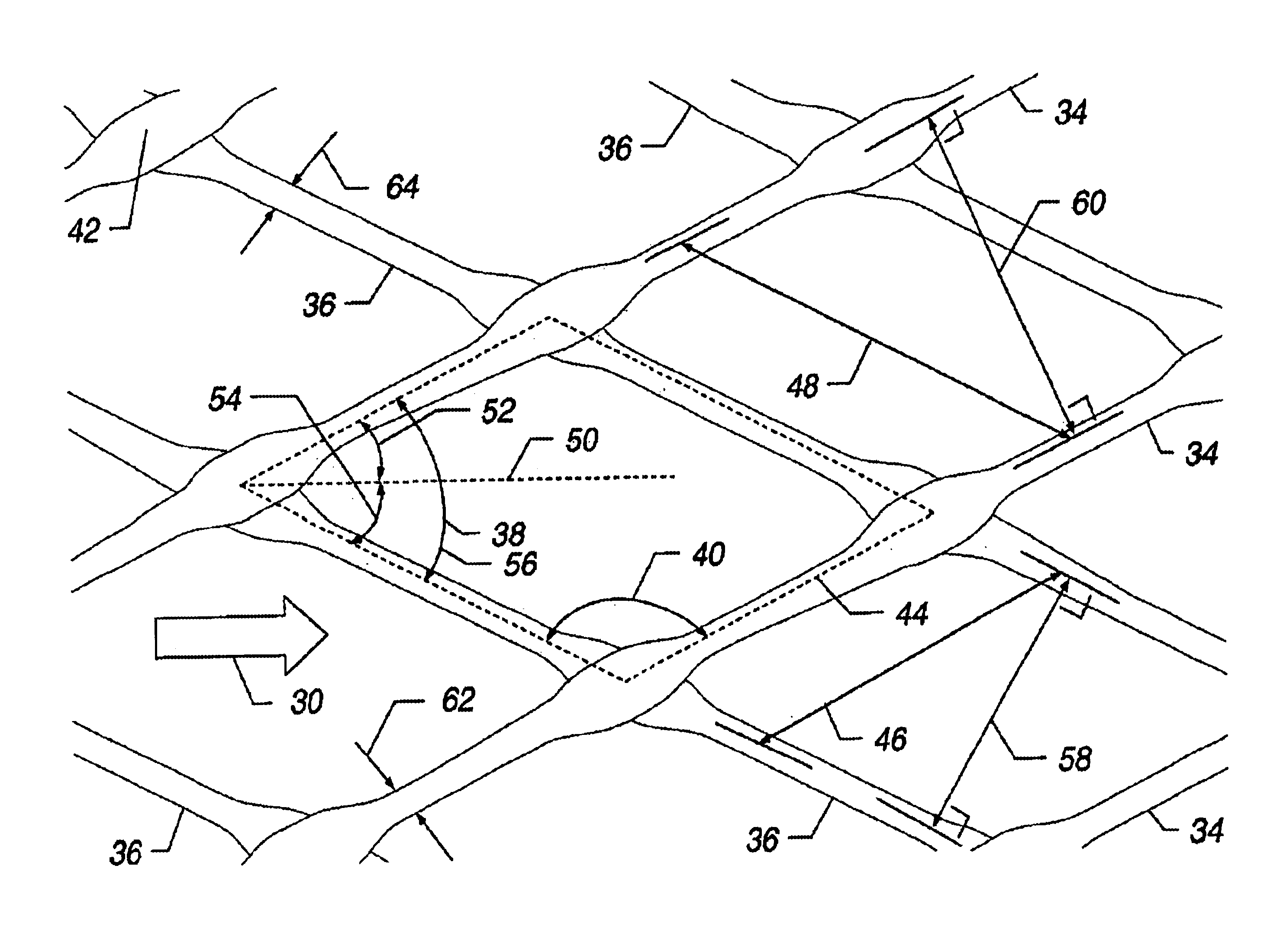
[0062]A feed spacer was made according to the process described below: As is typical in the art, a tubular net was formed by crossing two sets of filaments simultaneously extruded from two concentric, counter-rotating dies. The tubular structure was pulled over a mandrel and quenched in a water bath. After slitting, the resulting flat net had a width of 48.3 cm, a strand spacing of 2.12 mm, an average net thickness of 0.94 mm, and a characteristic angle of 85°. The slitting defined a machine direction for the net that was approximately parallel to the line bisecting the characteristic angle.

[0063]In parting from the conventional process of forming feed spacers for spiral wound elements, a tentering step was added to the process. The flat net was heated and stretched perpendicular to the machine direction. This tentering was done at 100° F. (Tentering may be performed over a wide range of temperatures, as described in U.S. Pat. No. 4,152,479. It was found that lower temperatures adva...

examples ii and iii

[0066]A process similar to that described in Example I was used to fabricate two other approximately symmetric feed spacers. Geometric properties measured for the two nets, before and after tentering, are shown in Table I. Based on width ratios, the tentering process stretched each net by more than a factor of two. Table I also lists the pressure gradient measured when water at 25° C. was caused to flow through the flat cell unit at 15 cm / sec. In these measurements, the machine direction of the feed spacer sheet was oriented perpendicular to the flow direction resulting in hydrodynamic angles of 47.5° and 60°.

[0067]

TABLE IExample 1Example 2Example 3Width of spacer sheet before48.348.353.3tentering (cm)Strand spacing before tentering (mm)2.122.122.07Average net thickness before0.940.840.81tentering (mm)Characteristic angle before tentering85.082.080.0(degrees)Width of spacer sheet after tentering110.5125.7114.3(cm)Strand spacing after tentering (mm)3.283.282.82Average net thickness a...


PUM

PropertyMeasurementUnit
Thicknessaaaaaaaaaa
Thicknessaaaaaaaaaa
Pressureaaaaaaaaaa

Abstract

The present invention is an improved feed spacer, spiral wound element incorporating said feed spacer, filtration system and a method for making and using the same. In one embodiment the present invention includes an improved spiral wound element having: a central collection tube with a plurality of openings along its length to receive permeate; at least one filtration envelope extending outwardly from and wound about the tube and at least one feed spacer sheet wound about the collection tube wherein the feed spacer sheet being in planar contact with the outer surface of at least one filtration envelope. The feed spacer sheet is a net comprising a first set of substantially parallel filaments crossed with a second set substantially parallel filaments to form a plurality of parallelograms having an acute angle less than 70°, the net oriented such that a line bisecting said acute angle is approximately parallel to the axis of the central collection tube and wherein the net has a strand thinning parameter greater than 1.3.

Description

FIELD OF THE INVENTION[0001]The present invention is an improved feed spacer, spiral wound element incorporating said feed spacer and a method for making and using the same.BACKGROUND[0002]Pressure-driven membrane separation processes allow a broad range of neutral and ionic species to be removed from fluids. In order of decreasing pore size, membranes are commonly classified into several categories: microfiltration (MF), ultrafiltration (UF), nanofiltration (NF) and reverse osmosis (RO). Microfiltration is used for removal of suspended particles having particle sizes greater than 0.1 microns. Ultrafiltration commonly excludes dissolved molecules having molecular weights greater than 5,000 daltons. Nanofiltration membranes pass at least some salts but usually have high retention of organic compounds having molecular weights greater than approximately 200 daltons. Reverse osmosis membranes have high retention of almost all species.[0003]An alternative means of characterizing membrane...

Claims


Application Information

Patent Timeline
IPC IPC(8): B01D63/10
CPCB01D63/10Y10T428/24132Y10T428/24058B01D65/08
Inventor JOHNSON, JON E.
Owner FILMTEC CORPORATION
Why Eureka
Try Eureka