

Semiconductor device and a method of manufacturing the same
- Summary
- Abstract
- Description
- Claims
- Application Information
AI Technical Summary
Benefits of technology
Problems solved by technology
Method used
Image

Examples
embodiment mode 1
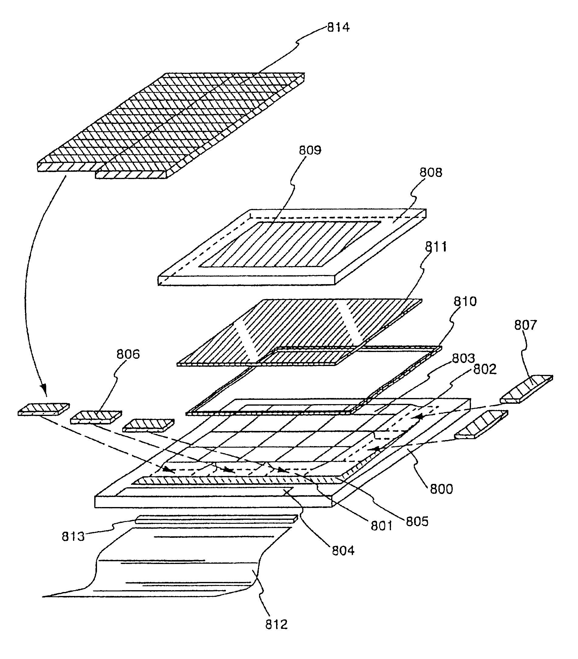
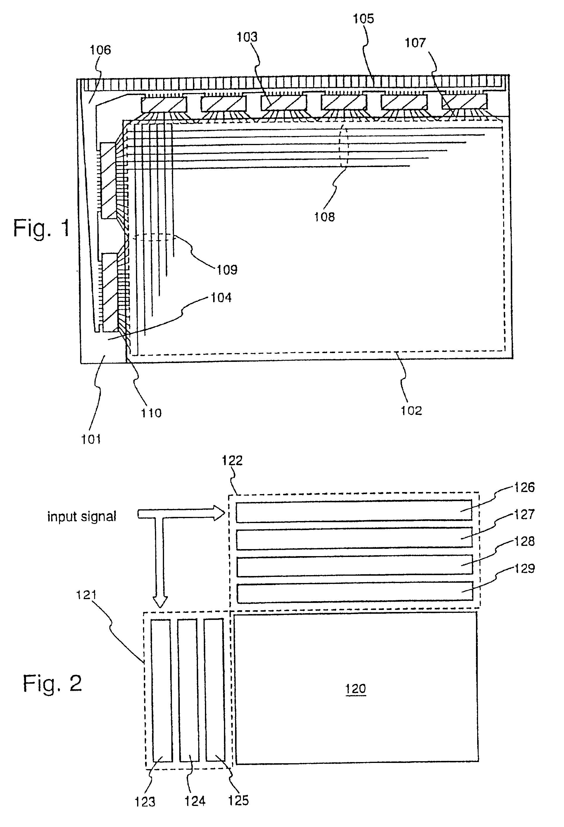
[0059]FIG. 1 is a diagram showing the structure of a display device of the present invention. A pixel region 102 is formed on a substrate 101. A second substrate 110, on which an opposing electrode is formed, is joined to the region in which the pixel region 102 has been formed, through a liquid crystal layer (not shown in the figure). The interval between the first substrate and the second substrate, namely the thickness of the liquid crystal layer, is determined by spacers, and is set from 3 to 8 μm for a nematic liquid crystal, and between 1 and 4 μm for a sumectic liquid crystal. It is preferable to use a non-alkaline glass such as aluminum borosilicate glass or barium borosilicate glass for the first substrate and the second substrate, and a thickness of 0.3 to 1.1 mm (typically 0.7 mm) is adopted, and therefore the thickness of the liquid crystal layer can be relatively ignored in outward appearance.
[0060]The pixel region 102 forms a matrix in which a scanning line (correspond...
embodiment mode 2
[0073]A method of manufacturing a TFT suitably applied mainly in a stick driver of a scanning line side is explained in this embodiment mode. Circuits such as a shift register circuit and a buffer circuit are formed in the stick driver on the scanning line side. The shift register circuit is assumed to be driven at 3 to 5 V, and the buffer circuit is assumed to be driven at 33 V. The TFT structuring the buffer circuit is required to have high voltage resistance, and therefore it is necessary for the film thickness of a gate insulating film to be thicker than that of other circuit TFTs. A manufacturing method thereof will be described with reference to FIGS. 6A to 6F and FIGS. 7A to 7E.
[0074]In FIG. 6A, a substrate such as a glass substrate, such as barium borosilicate glass or aluminum borosilicate glass, typically Corning Corp. #7059 or #1737, is used as a substrate 301. This type of glass substrate shrinks slightly due to the heating temperature, and if heat treatment processing i...
embodiment mode 3
[0105]The voltage resistance required by a stick driver TFT formed on a data line side is on the order of 12 V, but the operating frequency is equal to or greater than 50 MHz (for example, 65 MHz) at 3 V. A method of manufacturing a TFT suitable for such is explained in this embodiment mode.
[0106]Material quality with which it is possible to realize a high electric field effect mobility and a low subthreshold coefficient (S value) is required in a crystalline semiconductor film forming a channel forming region of the TFT. In other words, the crystalline semiconductor film having characteristics in which a defect level becomes trap centered or recombination centered, and in which the grain boundary potential is low. FIGS. 8A to 8C show one example of a method of manufacturing such a crystalline semiconductor film.
[0107]A substrate able to withstand heat treatment at 600° C. (preferably 950° C.) and having an insulating surface can be applied as a substrate 401 in FIG. 8A. From the vi...
PUM
 Abstract
Description
Claims
Application Information