
Method and system for coating and developing

Inactive Publication Date: 2005-04-26
TOKYO ELECTRON LTD
View PDF18 Cites 9 Cited by
  • Summary
  • Abstract
  • Description
  • Claims
  • Application Information

AI Technical Summary

Benefits of technology

[0008]The present invention is made in view of such a point, and its object is to provide a coating and developing treatment method and a coating and developing treatment system for preventing fine impurities at molecular level from adhering to a substrate such as a wafer.
[0013]According to the present invention, the treatment gas is supplied to form the treatment film on the surface of the coating film after the step of forming the coating film and before the step of exposing the substrate, whereby the substrate can be protected from impurities such as oxygen and water vapor in an atmosphere by this treatment film. Especially, if the impurities adhere to the substrate when the substrate is subjected to exposure processing, there is a possibility that the impurities absorb energy of a laser beam or the like used in exposure so that the exposure processing is not suitably performed. The aforesaid formation of the treatment film, however, enables suitable exposure processing. Further, the treatment film formed by the treatment gas is excellent in permeability, and permits a beam with a wavelength as short as about 157 nm to pass it. Accordingly, the adhesion of impurities to the coating film formed on the substrate is prevented while a predetermined circuit pattern can be precisely exposed onto this coating film.

Problems solved by technology

When the beam with the short wavelength is used, there is a fear that even impurities at molecular level such as oxygen, ozone, and water vapor which have been insignificant so far exert a bad influence on exposure processing, whereby a precise circuit pattern is not formed.
If only clean air is supplied as in prior arts, the adhesion of impurities onto the wafer can not be suppressed effectively since impurities such as oxygen are contained in the air, and moreover impurities adhering onto the wafer can not be removed.

Method used


Image

  • Method and system for coating and developing
  • Method and system for coating and developing
  • Method and system for coating and developing

Examples


Embodiment Construction

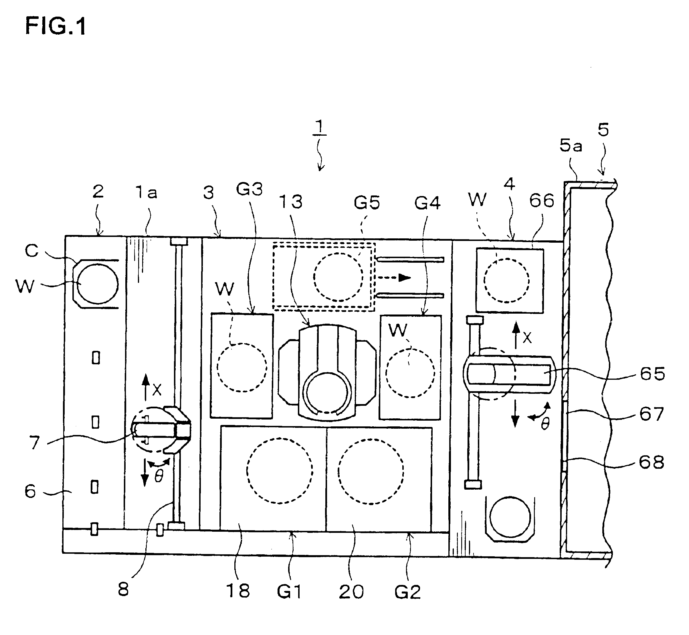
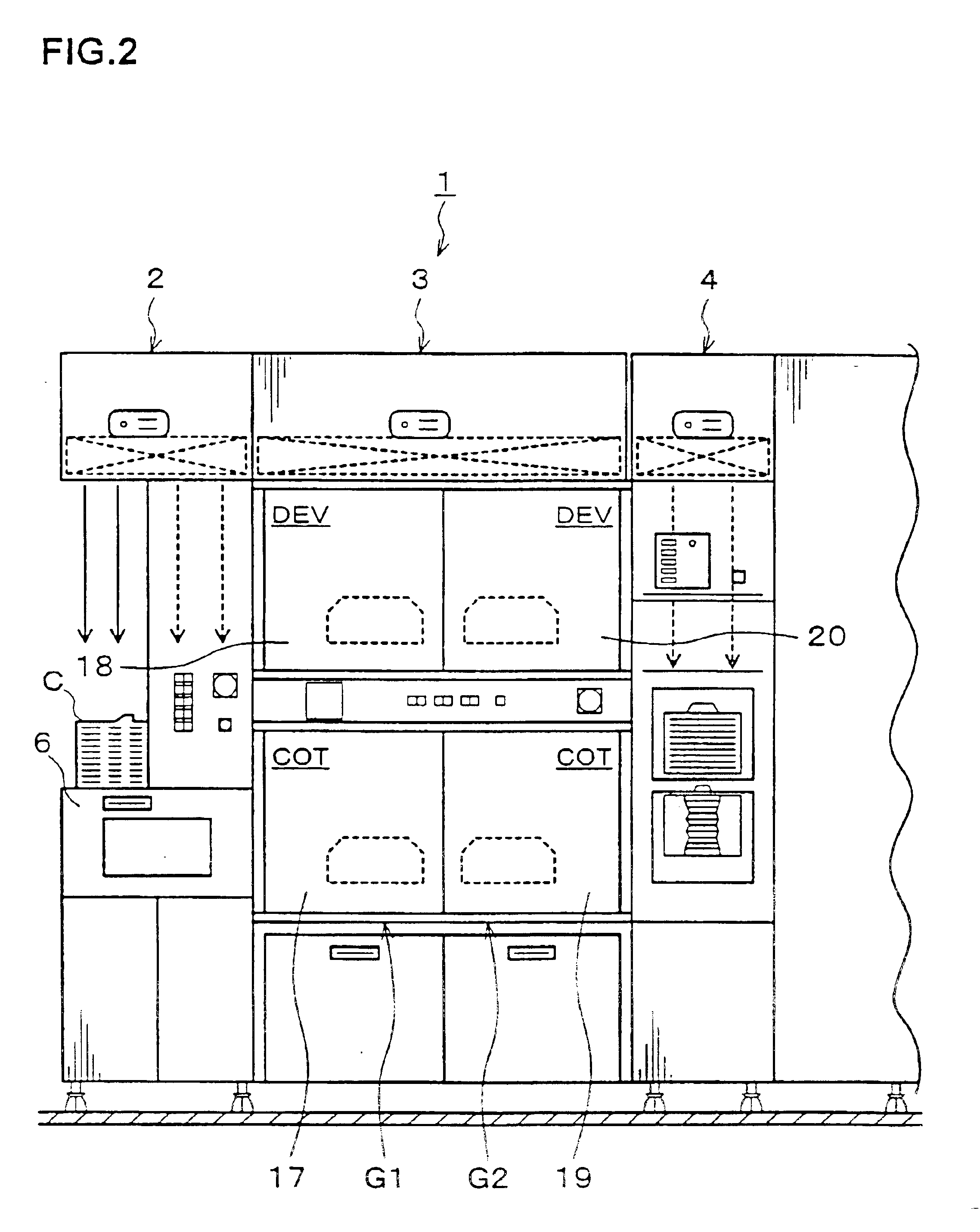
[0027]A preferred embodiment of the present invention will be explained below. FIG. 1 is a plan view of a coating and developing treatment system 1 according to this embodiment, FIG. 2 is a front view of the coating and developing treatment system 1, and FIG. 3 is a rear view of the coating and developing treatment system 1.

[0028]As shown in FIG. 1, the coating and developing treatment system 1 has a structure in which a cassette station 2 for transferring, for example, 25 wafers W per cassette, as a unit, from / to the outside into / from the coating and developing treatment system 1 and carrying the wafer W into / out of a cassette C, a processing station 3 as a treatment section where various kinds of treatment units each of which performs predetermined treatment for the wafers W one by one in a coating and developing process are stacked in multiple tiers, and an interface section 4 for receiving and sending the wafer W from / to an aligner 5 provided adjacent to the coating and developi...


PUM


Abstract

A coating and developing treatment system for performing coating and developing treatment. A coating treatment unit is configured to form a resist film on a substrate. A developing treatment unit is configured to develop the substrate. A heating / cooling unit includes a heat plate configured to continuously heat and a cooling plate configured to continuously cool in one casing the substrate on which the resist film has been formed by the coating treatment unit. A gas nozzle is configured to supply a treatment gas to the resist film formed on the substrate to form a protective film on a surface of the resist film. The gas nozzle is disposed on a cooling plate side in the heating / cooling unit. The gas nozzle is configured to move to a position above the substrate on the cooling plate during cooling at the cooling plate, to supply the treatment gas.

Description

BACKGROUND OF THE INVENTION[0001]1. Field of the Invention[0002]The present invention relates to coating and developing treatment method and system for a substrate.[0003]2. Description of the Related Art[0004]In photolithography of the process of fabricating a semiconductor device, for example, resist coating treatment for forming a resist film on the surface of a wafer, developing treatment for developing the wafer after pattern exposure, heat treatment and cooling treatment performed before the coating treatment, before and after exposure processing, and after the developing treatment, and the like are performed. Such treatment and processing are performed in treatment units provided individually, and these treatment units are unified as a coating and developing treatment system so as to continuously perform the aforesaid successive treatment and processing. The exposure treatment of a pattern is usually performed in an aligner disposed adjacent to the coating and developing treat...

Claims


Application Information

Patent Timeline
IPC IPC(8): G03F7/16G03F7/30G03F7/38H01L21/027
CPCG03F7/168H01L21/027
Inventor KITANO, JUNICHIMATSUYAMA, YUJIKITANO, TAKAHIROYAEGASHI, HIDETAMI
Owner TOKYO ELECTRON LTD
Learn More