
Method for making thin-film ceramic membrane on non-shrinking continuous or porous substrates by electrophoretic deposition

Active Publication Date: 2005-05-03
RGT UNIV OF CALIFORNIA
View PDF17 Cites 87 Cited by
  • Summary
  • Abstract
  • Description
  • Claims
  • Application Information

AI Technical Summary

Benefits of technology

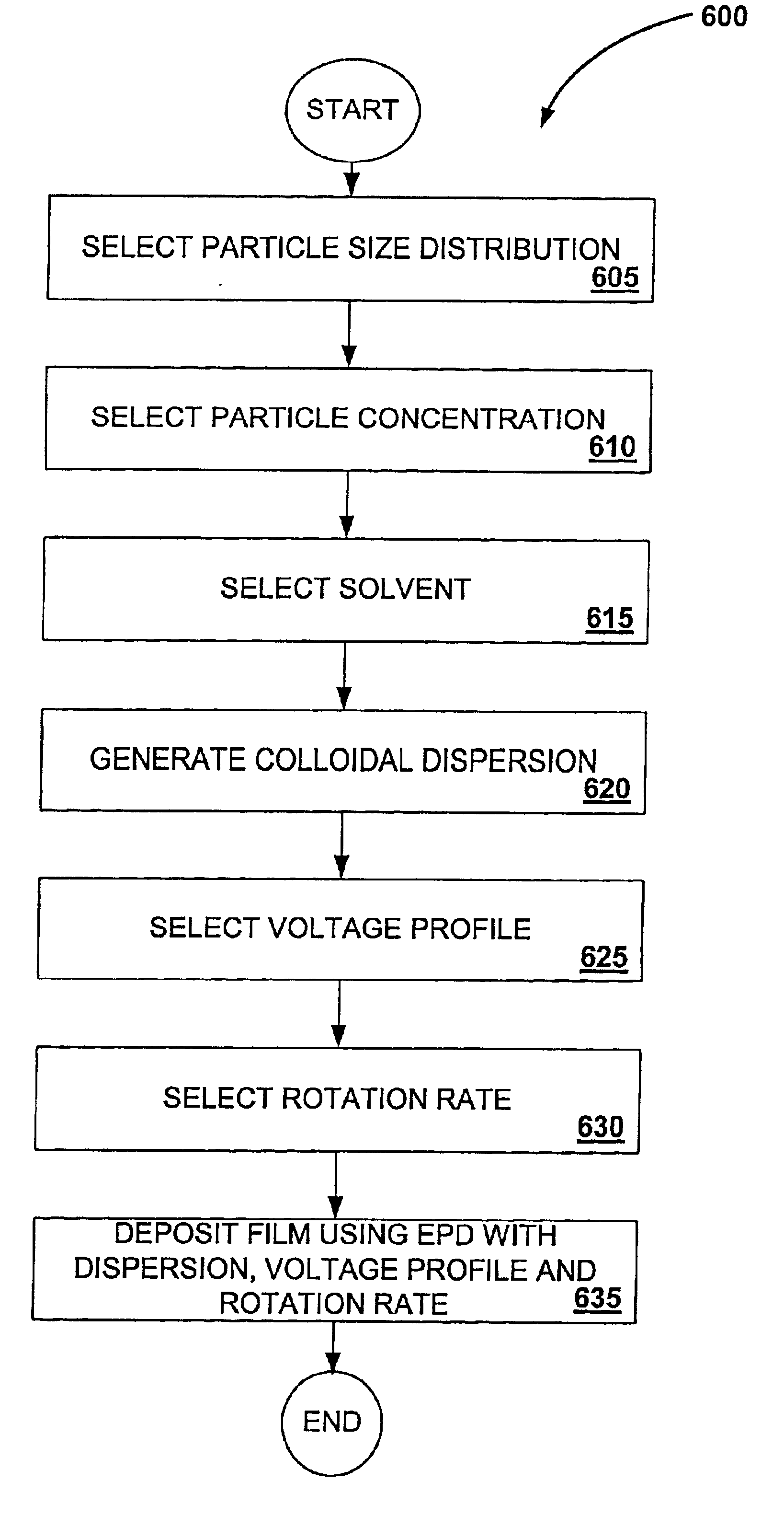
[0010]In general, the present invention provides low-cost, mechanically strong, highly electronically conductive porous structures for solid-state electrochemical devices and techniques for forming these structures. In particular, the invention provides a method of forming a ceramic film on a substrate using electrophoretic deposition (EPD). The method employs a colloidal dispersion of particles during EPD process where a distribution of particle sizes is selected to eliminate drying cracks in the ceramic film prior to firing of the ceramic coated substrate. The method may be used to provide a high-density green film which can be sintered on to a non-shrinking substrate. For instance, a thin film of YSZ with a high green density may be sintered on to a non-shrinking LSM substrate. In particular embodiments, the distribution of particle sizes used in the EPD process may be selected to reduce a firing temperature and a firing time during sintering of the film coated substrate. One aspect of the present invention provides a method of forming a ceramic coating on a solid state electrochemical device substrate. The method may be generally characterized as comprising: 1) providing a solid state electrochemical device substrate, the substrate consisting essentially of a material selected from the group consisting of a porous non-noble transition metal, a porous non-noble transition metal alloy, a porous cermet incorporating one or more of a non-noble non-nickel transition metal and a non-noble transition metal alloy, a porous cermet incorporating nickel, and a porous metal oxide or mixed metal oxide (such as LSM); 2) generating a suspension of ceramic material in a liquid medium; 3) applying a coating of the suspension of the ceramic material in a liquid medium to the substrate material using electrophoretic deposition; and 4) drying the coated substrate material where the ceramic material in the liquid medium is comprised of ceramic particles with a size distribution selected to eliminate cracking in the coating applied to the substrate during drying of the coated substrate. The size distribution of the ceramic particles may also be selected to reduce a firing time of the coated substrate or may be selected to reduce a firing temperature of the coated substrate. In one embodiment, the sizes of the ceramic particles may range from about 0.1 to 1 microns. The substrate may be planar or tubular shaped.
[0018]Another aspect of the present invention provides a method of forming a YSZ (Yittria Stabilized Zirconia) ceramic coating on an LSM (Lanthanum Strontium manganite) substrate using EPD (electrophoretic deposition). The method may be generally characterized as comprising: 1) providing the LSM substrate; 2) generating a suspension of YSZ material in a liquid medium, 2) applying a coating of the suspension of the YSZ material in a liquid medium to the LSM substrate material using EPD; and 3) drying the coated LSM substrate where the YSZ material in the liquid medium is comprised of YSZ particles with a size distribution selected to eliminate cracking in the coating applied to the LSM substrate during drying of the YSZ coated LSM substrate. The size distribution may be selected to reduce a firing time of the YSZ coated LSM substrate and to reduce a firing temperature of the YSZ coated LSM substrate. The sizes of the YSZ particles may range from about 0.1 to 1 microns.

Problems solved by technology

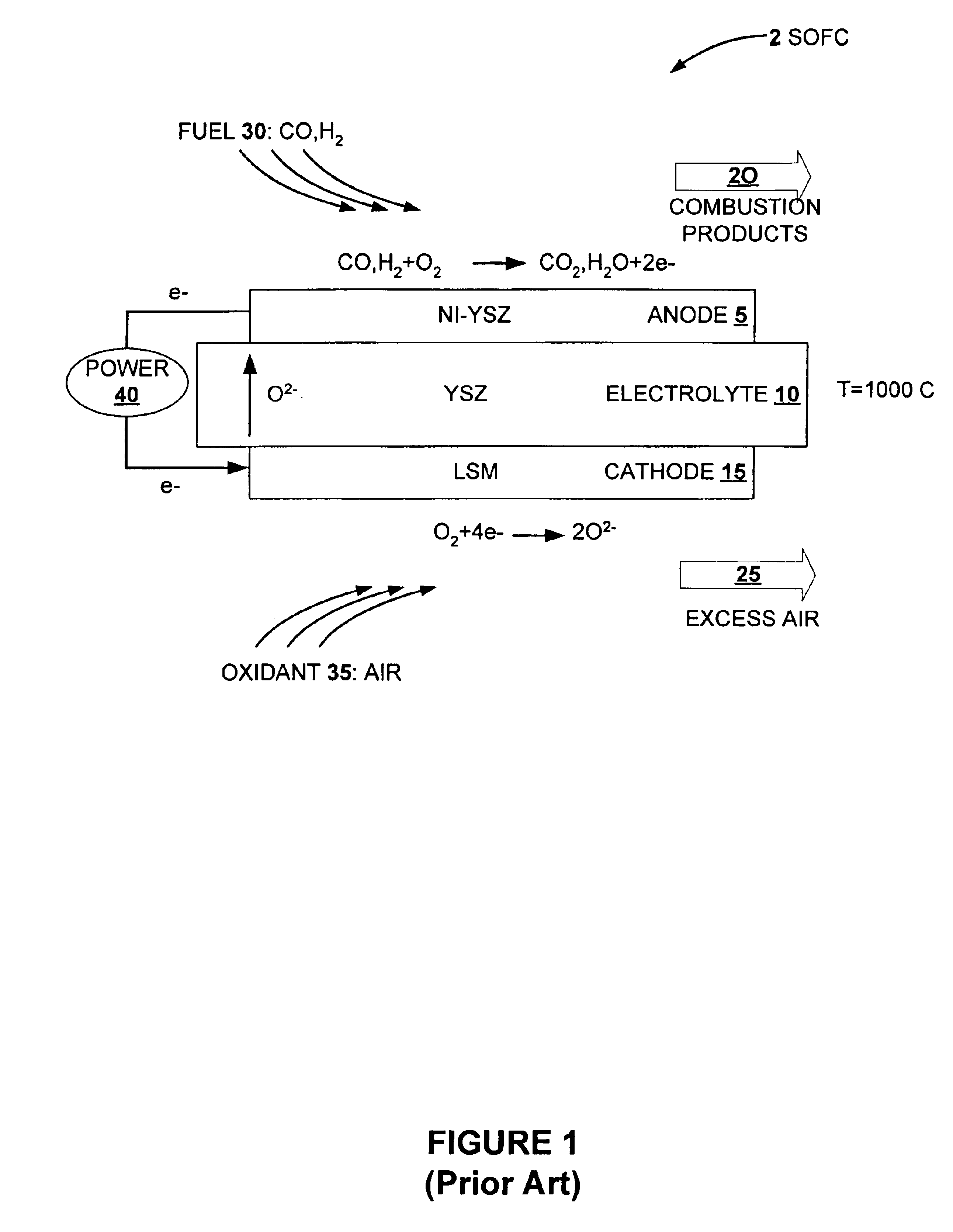
The ceramic materials used in conventional solid state electrochemical device implementations can be expensive to manufacture, difficult to maintain (due to their brittleness) and have inherently high electrical resistance.
The resistance may be reduced by operating the devices at high temperatures, typically in excess of 900° C. However, such high temperature operation has significant drawbacks with regard to the device maintenance and the materials available for incorporation into a device, particularly in the oxidizing environment of an oxygen electrode, for example.
Resistive loss attributable to these interconnects can also be significant.
However, these Ni-YSZ supported thin-film structures are mechanically weak, and will deteriorate if exposed to air on SOFC cool-down due to the oxidation of Ni to NiO in oxidizing environments.
Also, nickel is a relatively expensive material, and to use a thick Ni-YSZ substrate as a mechanical support in a solid state electrochemical device will impose large cost penalties.
Although this technique produces excellent films, it is inherently a batch process and capital intensive.
However, attempts to use colloidal deposition techniques failed due to the large volumetric changes in the electrolyte during sintering which are not compensated by concomitant shrinkage of the substrate.
Therefore it was recognized that a key issue for success would be to maximize the green density of the deposited film in order to minimize shrinkage of the film shrinkage and build up of stresses in the film which may lead to cracking or delamination.
Initial attempts to fabricate high quality films (onto a non-shrinking substrate) by electrophoretic deposition (EPD) according to established practices failed.

Method used


Image

  • Method for making thin-film ceramic membrane on non-shrinking continuous or porous substrates by electrophoretic deposition
  • Method for making thin-film ceramic membrane on non-shrinking continuous or porous substrates by electrophoretic deposition
  • Method for making thin-film ceramic membrane on non-shrinking continuous or porous substrates by electrophoretic deposition

Examples


example 1

of YSZ Film on LSM Substrate

[0091]A porous LSM (˜30% porosity) in a tubular form was obtained from Siemens Westinghouse Power corporation. A suspension of 0.5 g YSZ (0.3 micron particle size) / 100 ml IPA was dispersed using a sonic probe for 5 min. The tube was sealed at both ends using Teflon tape and an electrical contact was made using an alligator clip. The counter electrode was stainless steel tube selected such that the inner diameter was ˜5 mm larger than the outer diameter of the LSM tube. The tube and counter electrode were immersed in the YSZ suspension in a glass beaker provided with a stirring bar. The solution was stirred to prevent settling of the powder. Electrophoretic deposition was conducted by applying 30 μA / cm2 using a potentiostat / galvanostat for a period of 5 min. The current was turned off and the sample removed and allowed to air dry. The sample was placed in a MoSI2 heating element furnace and heated at a rate of 5° C. / min to 1300° C. and held for 4 hours. Th...


PUM

PropertyMeasurementUnit
Temperatureaaaaaaaaaa

Abstract

A disclosed method provides techniques for forming low-cost, mechanically strong, highly electronically conductive porous structures for solid-state electrochemical devices. In particular, a method of forming a ceramic film on a substrate using electrophoretic deposition (EPD) is described. The method employs a colloidal dispersion of particles during the EPD process where a distribution of particle sizes is selected to eliminate drying cracks in the ceramic film prior to firing of the ceramic film-coated substrate. The method may be used to provide a high-density green film which can be sintered on to a non-shrinking substrate. For instance, a thin film of YSZ with a high green density may be sintered on to a non-shrinking LSM substrate. In particular embodiments, the distribution of particle sizes used in the EPD process may be selected to reduce a firing temperature and a firing time during sintering of the film coated substrate.

Description

CROSS-REFERENCE TO RELATED APPLICATIONS[0001]This application is related to U.S. Provisional Application No. 60 / 278,554, METHOD FOR MAKING THIN-FILM CERAMIC MEMBRANE ON NON-SHRINKING CONTINUOUS OR POROUS SUBSTRATES BY ELECTROPHORETIC DEPOSITION, field Mar. 27, 2001, the disclosure of which is herein incorporated by reference for all purposes and this application is related to U.S. Provisional Application No. 60 / 335,404 METHOD FOR MAKING THIN-FILM CERAMIC MEMBRANE ON NON-SHRINKING CONTINUOUS OR POROUS SUBSTRATES BY ELECTROPHORETIC DEPOSITION, filed Oct. 30, 2001, the disclosure of which is herein incorporated by reference for all purposes.BACKGROUND OF THE INVENTION[0002]The present invention relates generally to the field of solid state electrochemical devices, and more particularly to methods of fabricating substrate, electrode and cell structures for solid state electrochemical devices.[0003]Solid state electrochemical devices are often implemented as cells including two porous el...

Claims


Application Information

Patent Timeline
IPC IPC(8): C25D13/02B01D67/00B01D69/10B01D71/02C04B41/50C04B41/87H01M4/88H01M8/12
CPCB01D67/0069B01D71/024C04B41/009C04B41/5042C04B41/87C25D13/02H01M4/8885H01M4/9033H01M8/1213H01M8/1226B01D69/10C04B41/4564C04B41/4578C04B35/016B01D2325/26C04B2111/00853H01M8/1253H01M2008/1293Y02E60/522Y02E60/525B01D2323/08Y02E60/50Y02P70/50B01D2323/081
Inventor VISCO, STEVEN J.JACOBSON, CRAIGDEJONGHE, LUTGARD C.
Owner RGT UNIV OF CALIFORNIA
Learn More