Fiber-coupled microsphere Raman laser

a laser and microsphere technology, applied in the field of lasers, can solve the problems of usually power-hungry devices, achieve the effects of convenient optical field transport, reduce the necessary threshold pump power, and improve overall efficiency

Inactive Publication Date: 2005-05-10
CALIFORNIA INST OF TECH +1
View PDF7 Cites 17 Cited by
  • Summary
  • Abstract
  • Description
  • Claims
  • Application Information

AI Technical Summary

Benefits of technology

[0013]The present invention is directed to a Raman laser and certain related methods. The devices and methods of the present invention are useful for creating laser signals having a frequency within a desired range by optically coupling an optical pump signal in a waveguide to a micro-cavity optical resonator in a manner which will produce stimulated Raman Scattering effect (“SRS”). The amount of SRS is dependent on the relative positioning of the waveguide to the micro-cavity resonator, the characteristics (high-Q and size) of the

Problems solved by technology

Because Raman lasers require enormous intensities

Method used


Image

  • Fiber-coupled microsphere Raman laser
  • Fiber-coupled microsphere Raman laser
  • Fiber-coupled microsphere Raman laser

Examples


Embodiment Construction

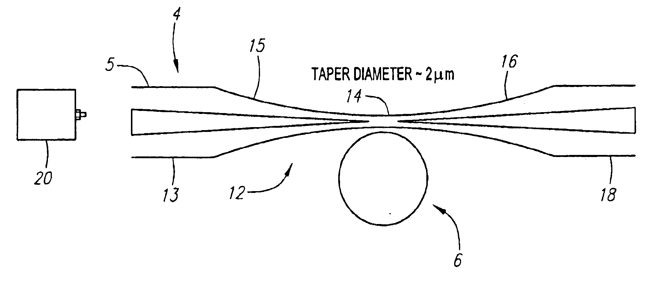
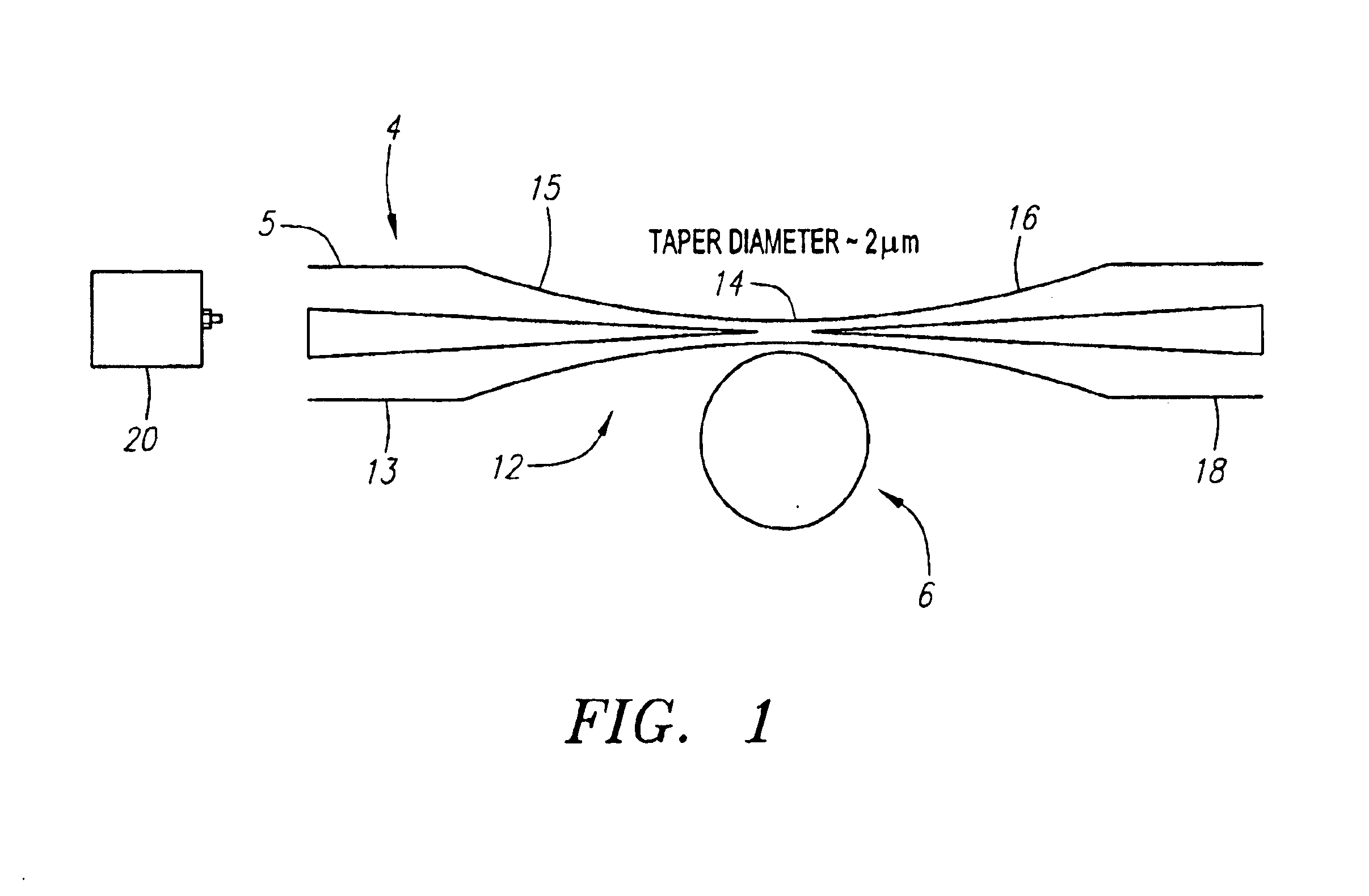
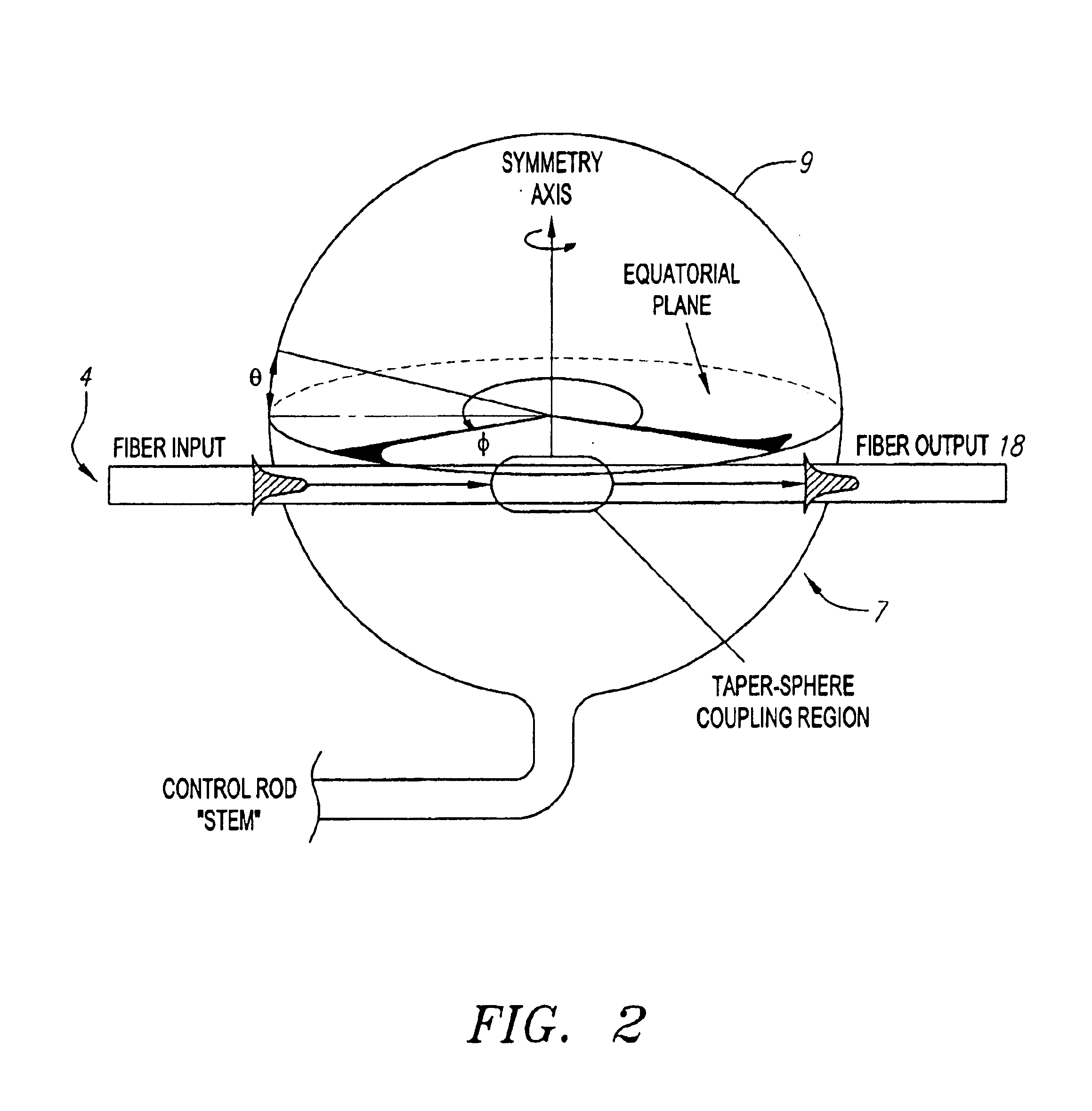
[0028]For the purposes of discussion the terms resonance and optical mode will be used interchangeably herein. Likewise, the terms micro-cavity resonator and micro-resonator will be used interchangeably herein. Of all cavity geometries, micrometer-sized dielectric spherical resonators are believed to be one of the best in terms of their ability to store energy for long periods of time within small volumes. In the sphere, light orbits near the surface, where long confinement times (high Q) effectively wrap a large interaction distance into a tiny volume. In this configuration, the physics within the sphere enters a nonlinear regime wherein conventional rules for light propagation break down. In the preferred embodiment, the molecules of the glass bead itself are distorted, resulting in a process called Raman emission and lasing. Because Raman lasers require enormous intensities to function, they are usually power-hungry devices. The present invention uses the physics of the micro-res...


PUM


Abstract

The present invention is a Raman laser and methods related thereto. In the preferred embodiments, the Raman laser comprises a laser pump signal in a fiber waveguide which is optically coupled to a micro-resonator through a fiber taper. The micro-resonator is constructed from a material that has a high Q when it is formed into a micro-resonator and is phase matched to the waveguide. The lasing frequency can be determined based upon the pump input or the micro-resonator material. In the preferred embodiments, the micro-resonator is constructed from a fused silica material. The present invention provides a compact laser with improved emissions and coupling efficiencies and the ability to use stimulated Raman scattering effects to create lasers having frequencies that are otherwise difficult to obtain. Alternative configurations include multiple micro-resonators on a single fiber waveguide and/or utilizing multiple waveguides attached to one or more micro-resonators. The Raman laser can be made to operate in a continuous-wave as opposed to self-pulsing mode.

Description

[0001]This application claims priority on U.S. provisional application No. 60 / 304,224, filed Jul. 9, 2001, and entitled, “Fiber-Coupled Microsphere Raman Laser.” The disclosure of the foregoing is incorporated by reference herein as if set forth in full hereat.[0002]The U.S. Government has certain rights in this invention pursuant to Grant No. N00014-99-1-0661 awarded by the United States Office of Naval Research.FIELD OF INVENTION[0003]The field of the invention relates to lasers and certain related methods, and in particular to Raman lasers and related methods.BACKGROUND OF THE INVENTION[0004]The frequency of the output of a laser can be important to its use and functioning. By way of example, currently, the telecommunications industry uses frequencies in the 1550 m range. Indeed, specific frequency outputs are often needed for both scientific research as well as commercial applications. As such, much time and effort has been spent attempting to utilize the stimulated Raman scatte...

Claims


Application Information

Patent Timeline
IPC IPC(8): H01S3/30H01S3/081H01S3/083H01S3/08
CPCH01S3/30H01S3/08H01S3/094053H01S3/083
Inventor VAHALA, KERRY J.SPILLANE, SEAN M.KIPPENBERG, TOBIAS J.
Owner CALIFORNIA INST OF TECH
Why Eureka
Try Eureka