
Plate-frame heat exchange reactor with serial cross-flow geometry

Inactive Publication Date: 2005-05-17
FORD GLOBAL TECH LLC
View PDF2 Cites 30 Cited by
  • Summary
  • Abstract
  • Description
  • Claims
  • Application Information

AI Technical Summary

Benefits of technology

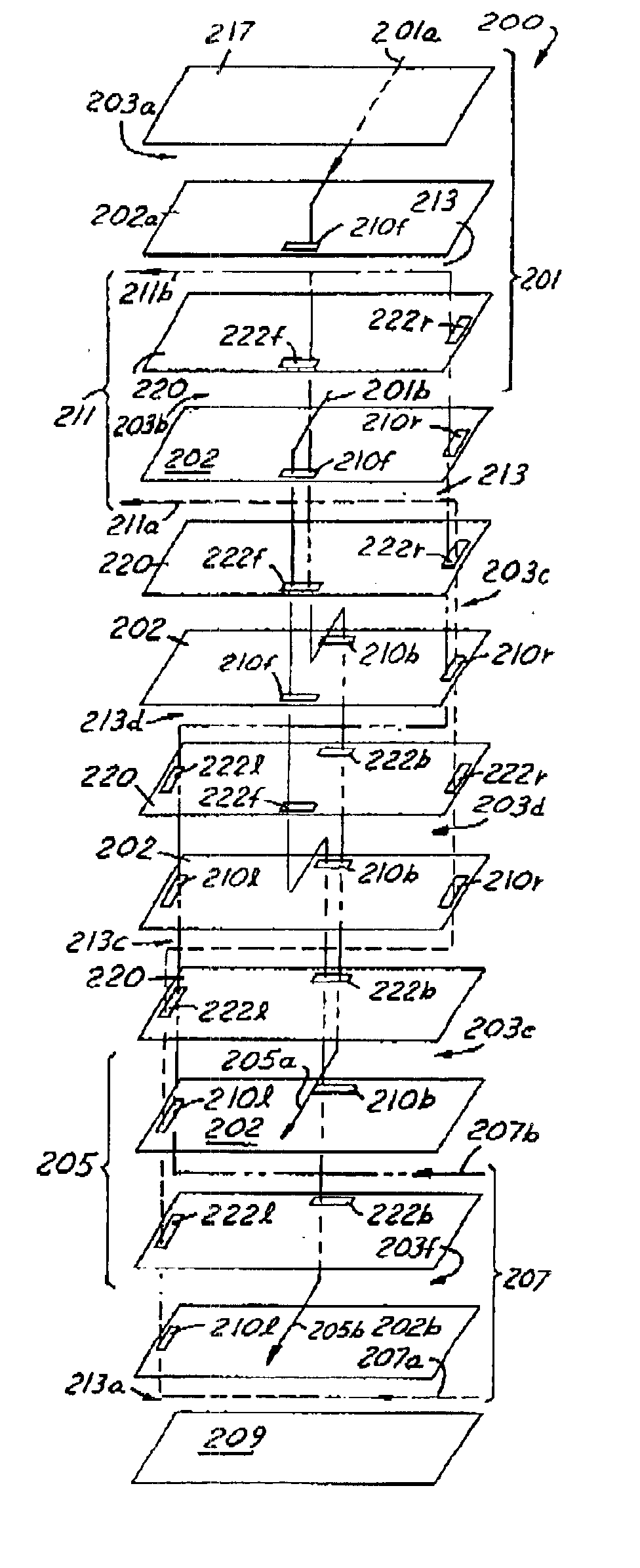
[0011]The new arrangement has several advantages over the massively parallel reactor systems. First, the new arrangement increases the Reynold's number of the flows to greatly improve the heat transfer characteristics and reactant mixing characteristics of the reactor, thereby reducing the reactor size by half or more. Second, the new arrangement allows for constructing reactors where reactant addition is possible at many distributed points along the serial flow using simple mechanical features in order to control hot spots or other undesirable chemical reactions. Third, the new arrangement greatly simplifies manifolding of the flows and reduces the number of distinct components required in the heat exchanger. Fourth, the heat exchanger plate geometry is not constrained to long narrow ducts to create high aspect ratio counterflow designs.

Problems solved by technology

This reaction is highly endothermic, and typically requires large amounts of catalyst to promote the reaction.
First, massively parallel construction leads to low flow velocity (and corresponding Reynolds number) and low laminar flow. This drawback is critical because lower laminar flow reduces heat transfer rates and reduces reactant mixing in the reactor structures, which along with the Reynolds number are factors in sizing the reformer. Hence, a lower Reynolds number requires a larger reformer, which adds to the cost of the reformer system.
Second, manifolding in the massively parallel construction may be fairly complex. This complexity may cause poor fluid distribution with “dead zones”, where little flow occurs, which reduces heat exchange effectiveness.
Third, controlled internal release of any one reactant is very difficult as the short reaction zone is only accessible from either end of the plate. This point is particularly important if the heat exchanger structure is to be used as a catalytic burner. Catalytic burning on the heat exchanger walls improves heat transfer locally by obviating convective heat transfer from the gas phase to the wall because the catalysts are located on the wall itself. Unfortunately, if fuel or oxidant levels are not controlled, the catalytic burning can occur at too high a rate, causing local increases in metal temperature referred to as hot spots. Hot spots significantly weaken the structure and may cause mechanical failure. Because of this fact, systems with catalytic burning on the wall must use exotic materials and dilute combustion gases to lower temperatures to an acceptable level, which negatively impacts both cost and efficiency.

Method used


Image

  • Plate-frame heat exchange reactor with serial cross-flow geometry
  • Plate-frame heat exchange reactor with serial cross-flow geometry
  • Plate-frame heat exchange reactor with serial cross-flow geometry

Examples


Embodiment Construction

)

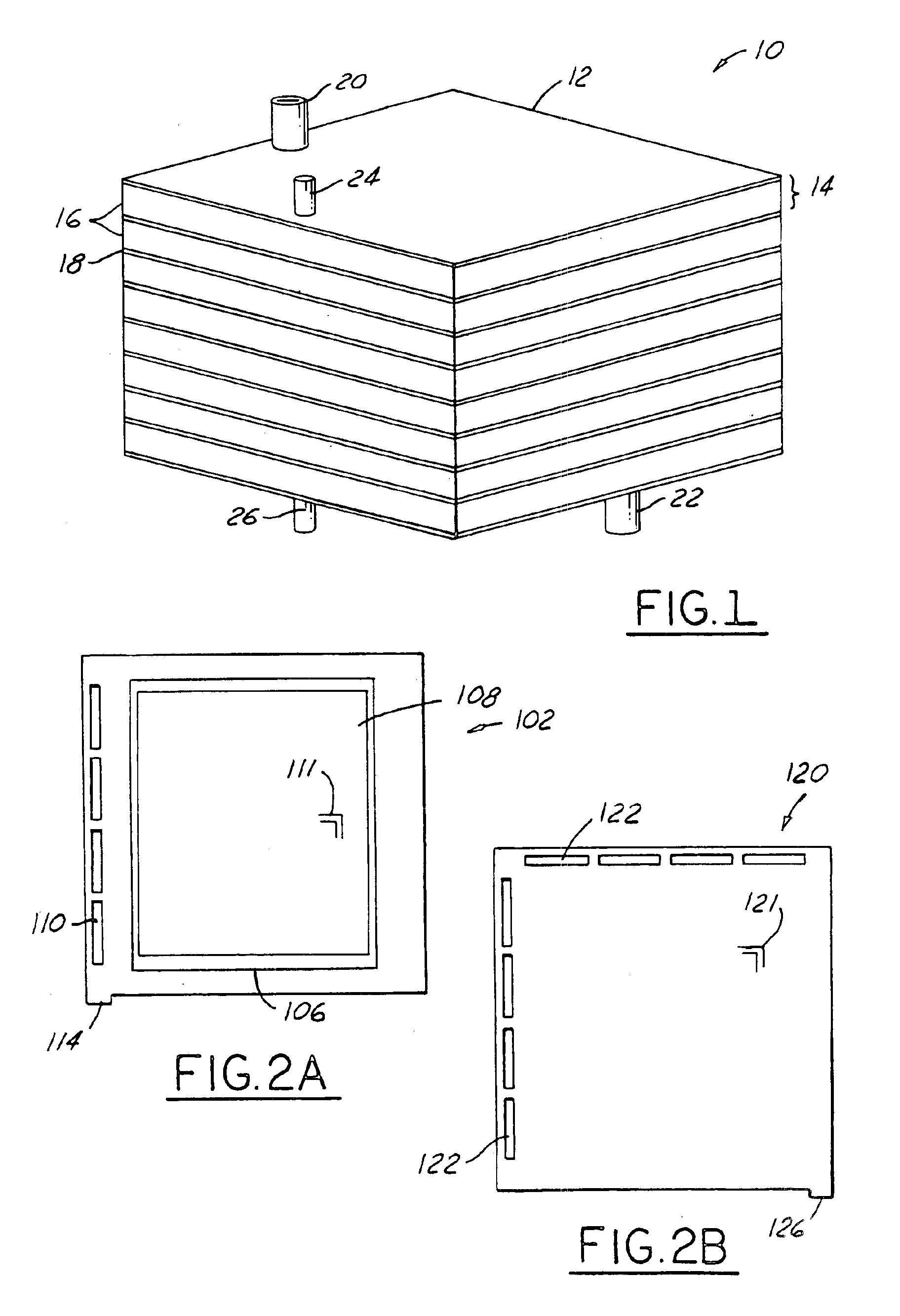
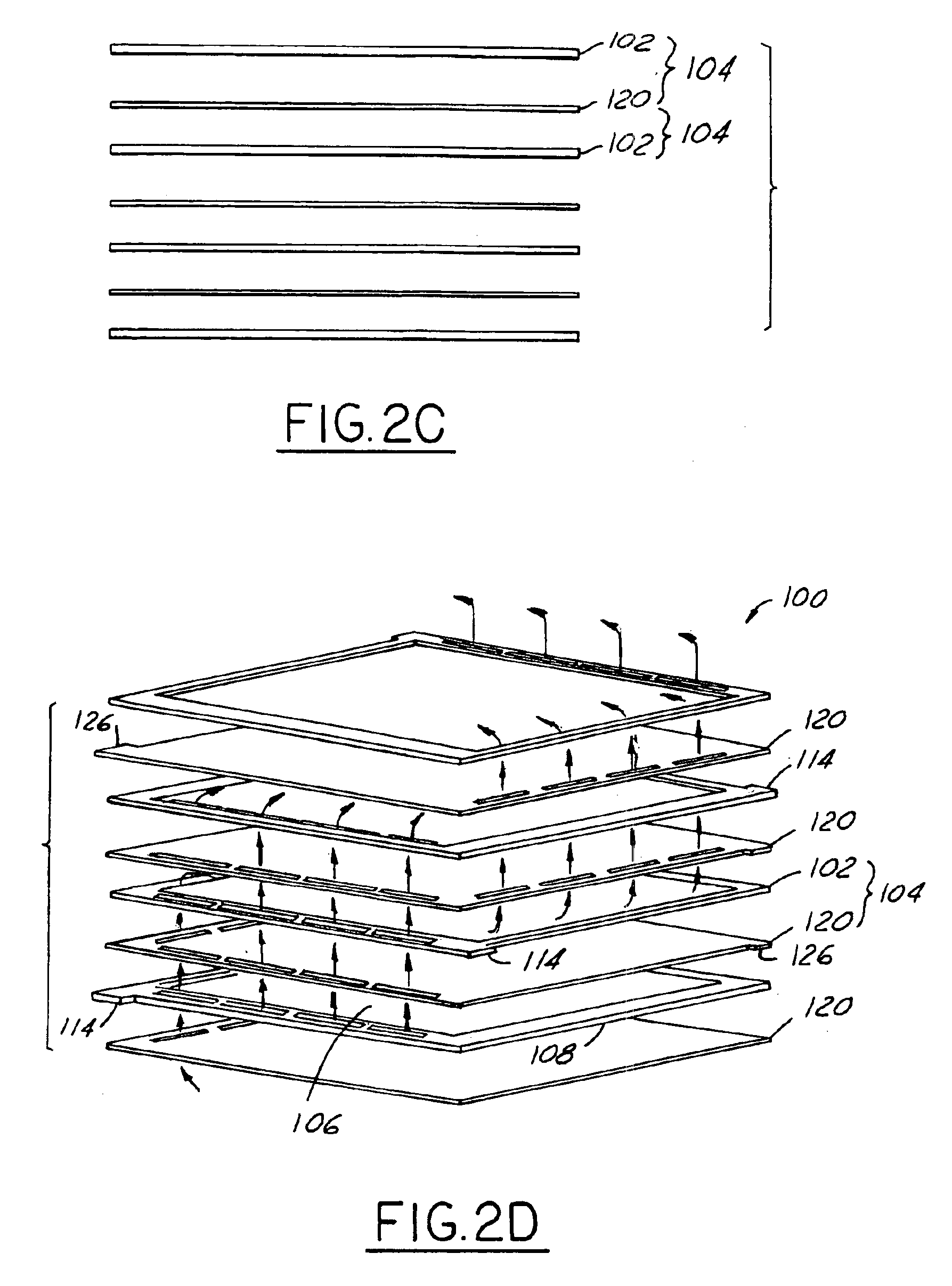
[0021]Referring now to FIG. 1, a fuel processing assembly 10 which forms a portion of a typical fuel cell power plant is depicted. The assembly 10 includes a plate frame heat exchange reformer 12 for converting hydrocarbon fuels into hydrogen that is used by electrochemical fuel cells (not shown) to generate electricity. The reformer 12 is primarily comprised of a series of stacked cells 14. Each stacked cell 14 is comprised of a header sheet 16 and an interleaved sheet 18. The reformer 12 has an intake port 20 for receiving feed gas, typically gasoline, natural gas, or some other type of hydrocarbon, from a reservoir (not shown) and an outlet port 22 for removing the heated reformed feed gas from the reformer 12. The feed gas may also comprise any combination of water, oxygen, nitrogen, carbon monoxide, carbon dioxide, hydrogen, and partially reacted fuel. The reformer 12 has a burner inlet port 24 for receiving heated burner exhaust gas and / or a partially or wholly unreacted mixt...


PUM

PropertyMeasurementUnit
Timeaaaaaaaaaa
Flow rateaaaaaaaaaa
Sizeaaaaaaaaaa

Abstract

A plate-frame heat exchange reactor having a serial cross-flow geometry. This is accomplished by designing a plate-frame heat exchanger wherein the flow of feed gas in one cell of the reactor flows perpendicular to the flow of burner exhaust within the next adjacent cell. The improved reactor increases the Reynold's number of the flows as compared with a massively parallel design to improve heat transfer and reactant mixing characteristics, thereby reducing reactor size by half or more. The serial cross-flow arrangement allows for constructing reactors where feed gas addition is possible at many distinct points along the serial flow in order to control hot spots or other undesirable chemical reactions. The new arrangement also greatly reduces manifolding of the flows and reduces the distinct components of the reactor.

Description

TECHNICAL FIELD[0001]The present invention relates generally to heat exchange systems and more particularly plate-frame heat exchangers.BACKGROUND[0002]Plate-frame heat exchangers are commonly employed to provide relatively compact devices with low-pressure drop. Such devices are typically deployed in weight / volume critical applications such as automotive air-conditioning evaporators, gas turbine recuperators, fuel cells, and liquid—liquid industrial heat exchangers. Because these applications are sensitive to both heat exchanger size and pressure drop through the fluid passages, typical plate-frame heat exchangers have a series of individual heat exchanger cells arrayed substantially in parallel (i.e. each cell (hot fluid side and cold fluid side) has the same temperature distribution as every other cell in the stack of cells comprising a completed heat exchanger)).[0003]Because of the success of the plate-frame approach to heat exchange design, it has been widely adapted to chemic...

Claims


Application Information

Patent Timeline
IPC IPC(8): F28D9/00
CPCF28D9/005F28F13/18
Inventor JAMES, BRIAN DAVIDLOMAX, FRANKLIN DELANOBAUM, GEORGE NEWELL
Owner FORD GLOBAL TECH LLC
Learn More