Power load-leveling system and packet electrical storage

a power load leveling and packet technology, applied in emergency power supply arrangements, process and machine control, instruments, etc., can solve the problems of ineffective utilization of the design capacity of the power plant for the rest of the sixteen hours of the day, more power needs, and inability to make efficient use of the resulting power plant, etc., to achieve more long-term power, improve power quality, and reduce or even eliminate anomalies

Inactive Publication Date: 2005-05-31
AMERICAN ELECTRIC POWER CO INC
View PDF39 Cites 212 Cited by
  • Summary
  • Abstract
  • Description
  • Claims
  • Application Information

AI Technical Summary

Benefits of technology

[0010]An inherent benefit of the present invention is the ability to substantially reduce or even eliminate anomalies such as power “surges”, “spikes”, and “skips”, thereby improving what is generally referred to as “power quality”. These phenomena are the unfortunate, and practically unavoidable result of moving electrical energy (i.e., electrons) over miles of distribution and transmission lines to end users. Power quality problems can occur for a number of reasons including, for example, electrical system design errors, electrical system construction errors, grounding errors, harmonics and load interactions. While these anomalies are not very common when one considers the total amount of energy delivered each day to any area, they nevertheless can result in significant problems for end users. For example, in this age of computer usage, an energy spike or skip, however brief, can cause electronic documents to be lost, or worse yet, can cause computer system damage. In contrast to the concept of electrical energy storage described above, the electrical energy that must be provided for maintaining power quality is extremely brief in duration. For example, it has been found that most power quality phenomenon occurs within 1 AC cycle or less, and that 10 cycles is usually more than sufficient to relax any momentary disturbance in the supply voltage. Thus, for purposes of the present application, power quality maintenance or improvement is generally defined to mean

Problems solved by technology

First, populations in practically every country of the world have increased, resulting in more power needs.
Second, consumer products frequently are designed to use electrical energy in order to operate.
The problem with using peak demand requirements to determine power plant capacity, is that it does not make for efficient use of the resulting power plant.
For example, if a peak demand period in a given area is X kilowatt-hours and that demand is only required for a period of eight hours each day, and the average demand for the rest of the day is half of X, then the design capacity of that power plant for the other sixteen hours of each day is not being effectively utilized.
Using peak demand requirements also results in an inefficient use of the distribution and transmission systems used by the

Method used


Image

  • Power load-leveling system and packet electrical storage
  • Power load-leveling system and packet electrical storage
  • Power load-leveling system and packet electrical storage

Examples


Embodiment Construction

)

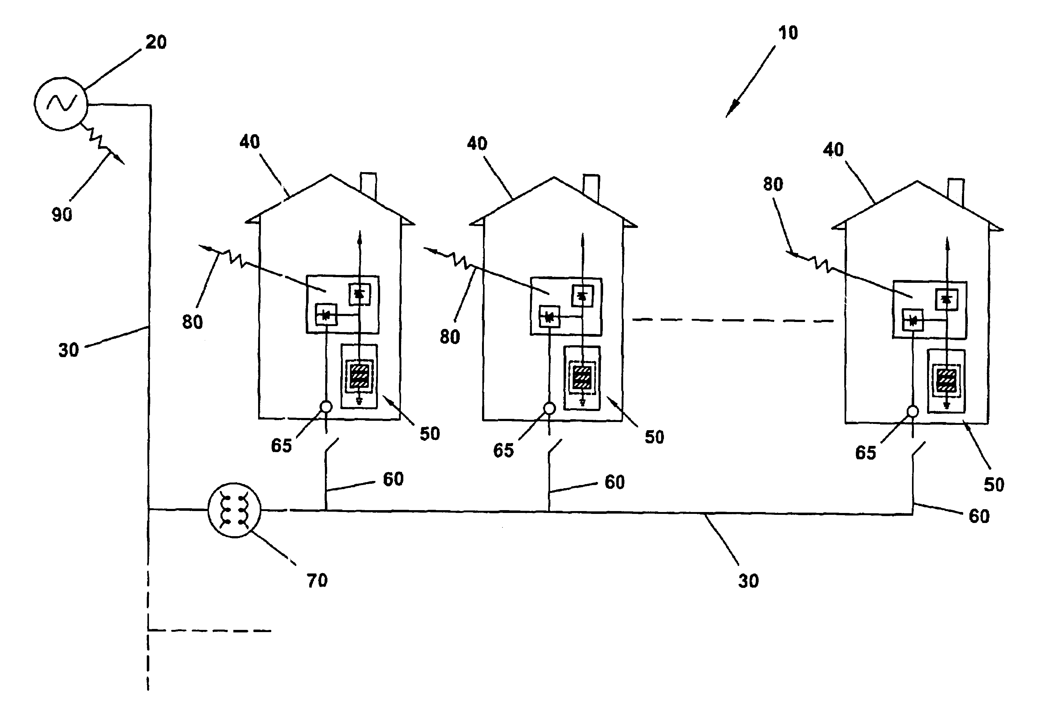
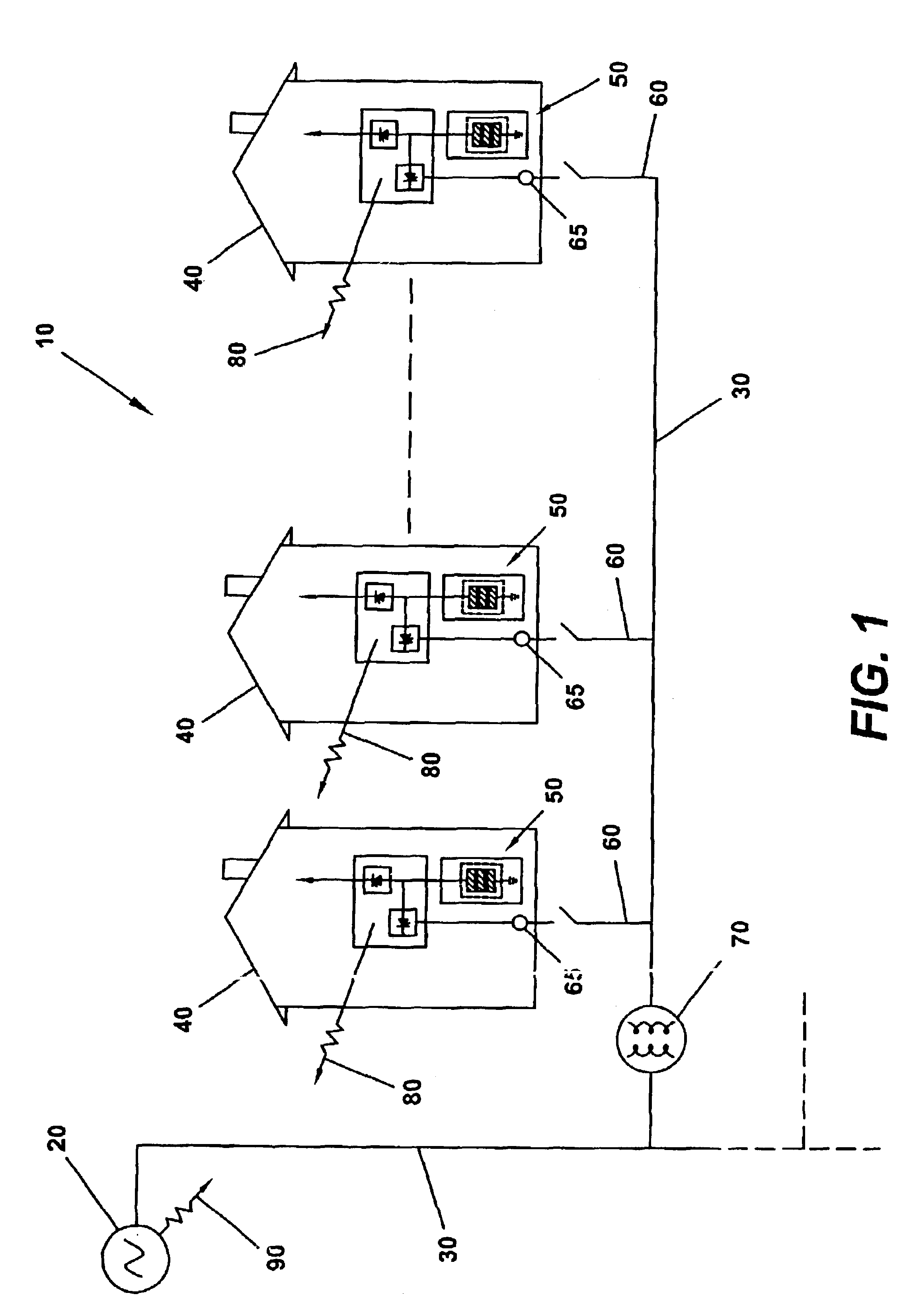
[0021]Referring now to the drawings and FIG. 1, there is shown a schematic representation 10 of an exemplary embodiment of the present invention. In this embodiment, electrical energy is produced at a power plant 20 and is distributed through conventional energy transmission and distribution lines 30 to homes 40 where a capacitor storage device 50 is located. The power plant 20 may be a conventional fossil-fuel burning or nuclear power plant or, alternatively, may be a solar power, wind power, hydroelectric power, or other alternate power source. Each home may have one or more capacitor storage devices 50, each having one or more capacitors (for example, in the basement of the home) that is electrically connected, such as via a service entrance 60, to the transmission and distribution lines 30 through an electric meter 65 or similar device in order to receive an electrical charge. The electrical charge may be delivered in the form of a “packet” of electrical energy of undetermined ...


PUM


Abstract

A large-scale, capacitor-based electrical energy storage and distribution system capable of effectuating load-leveling during periods of peak demand on a utility, and of effectuating a cost savings associated with the purchase of electrical energy. A capacitor or multitude of capacitors may be charged with electrical energy produced by the utility, such as during periods of low demand or low cost, and discharged during periods of high electrical energy consumption or high electrical energy cost. One or more capacitors may be located at a consumer's residence or business. Alternatively, a farm of capacitors may be provided at or near a utility, or at or near a location experiencing high demand. In another embodiment, one or more capacitors may be located in or on a vehicle, such as an automobile, a truck, or a train of a light rail system.

Description

CROSS-REFERENCE TO RELATED APPLICATIONS[0001]This application is a continuation of U.S. application Ser. No. 09 / 974,240, filed Oct. 10, 2001, now U.S. Pat. No. 6,522,031, which claims the benefit of U.S. Provisional Application No. 60 / 239,560, filed on Oct. 10, 2000, both of which are expressly incorporated herein by reference.BACKGROUND AND SUMMARY OF THE INVENTION[0002]The present invention relates generally to electrical energy supply and distribution, and more particularly, to a power load leveling system including energy packet storage components. Electrical energy generation and distribution has been a mainstay for residential and commercial energy needs for societies all over the world for many years. Various forms of electrical energy generation have existed for some time now, including coal fired power plants, nuclear power plants, hydroelectric plants, wind harness plants, and others. All of these forms of electrical energy generation are well known to those of skill in th...

Claims


Application Information

Patent Timeline
IPC IPC(8): H02J3/32H02J3/28H02J5/00H02J7/34G05F1/66
CPCH02J3/28H02J7/345H02J5/00H02J3/32Y02P80/10H02M5/40
Inventor PROVANZANA, JOHN H.SCHNEIDER, JOHN M.NOURAI, ALIWALBORN, WARREN W.WARE, BRENDAN J.
Owner AMERICAN ELECTRIC POWER CO INC
Why Eureka
Try Eureka