Time division multiplex data recovery system using close loop phase and delay locked loop

a data recovery and time division multiplex technology, applied in the direction of digital transmission, pulse automatic control, electrical equipment, etc., can solve the problems of increasing the power required, large hunting jitter of the data loop receiver, and the great disadvantage of high power requirements, so as to reduce the number of times of data recovery, reduce the amount of power, and reduce the effect of duty cycl

Inactive Publication Date: 2005-05-31
TEXAS INSTR INC
View PDF6 Cites 135 Cited by
  • Summary
  • Abstract
  • Description
  • Claims
  • Application Information

AI Technical Summary

Benefits of technology

[0008]A time division multiplex data recovery system using a closed-loop phase locked loop (PLL) and a delay locked loop (DLL). In other words, one closed loop comprises both a phase locked loop (PLL) and a delay locked loop (DLL) in a novel time division multiplex data recovery system. This new architecture comprises a 4 stage Voltage Controlled Oscillator (VCO) used to generate 8 clock signals, 45 degrees phase shifted from one another, for 8 receivers to do the oversampling in the data recovery block. The receivers 44 each trigger on only the rising edge of the clock to alleviate duty cycle issues. A phase interpolator 44 tracks the received data signal and feeds it back to the Phase / Frequency Detector (PFD) 34 to adjust the measurement position of the sampling clock 70. The PFD 34 has a second input of the reference clock which the PFD uses along with the interpolator input to correct the frequency and phase of the PLL. The PLL operates at a high bandwidth. The DLL's bandwidth is several orders lower than the PLL. The DLL activates only a multiplexer and an interpolator continuously, thereby drawing a minimum amount of power.

Problems solved by technology

Although this system has the advantage of being stable in a noisy environment due to the high bandwidth of the PILL and passive DLL clock recovery, this system also has the great disadvantage of requiring high power due to use of the high speed clock which necessitates a huge clock buffer and additional digital logic processing the output of the receiver.
Also disadvantageous is that the majority of the system operates digitally thus increasing the power required as the frequency of operation increases.
Although this system has the advantages of operating at high speeds due to the time division multiplex of 20 slow clocks(assuming a 1:10 deserializer), low power operation due to no clock buffer requirement (clock fanout is one, i.e. capacitive load is very small) and few digital circuits in operation, and activity of all the transmitter and receivers is at a 10% duty cycle due to the time division multiplex, it also has the disadvantage of the data loop receiver having large hunting jitter and the system is not stable in noisy environments due to the extremely narrow bandwidth of operation.

Method used


Image

  • Time division multiplex data recovery system using close loop phase and delay locked loop
  • Time division multiplex data recovery system using close loop phase and delay locked loop
  • Time division multiplex data recovery system using close loop phase and delay locked loop

Examples


Embodiment Construction

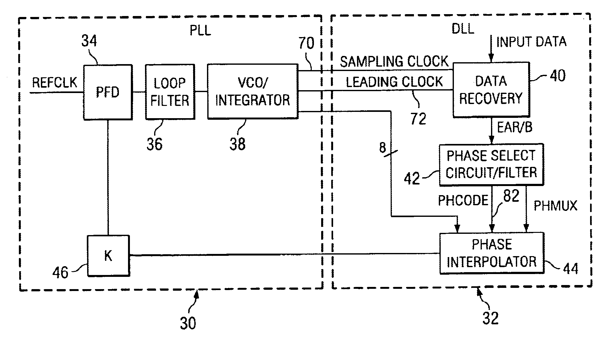
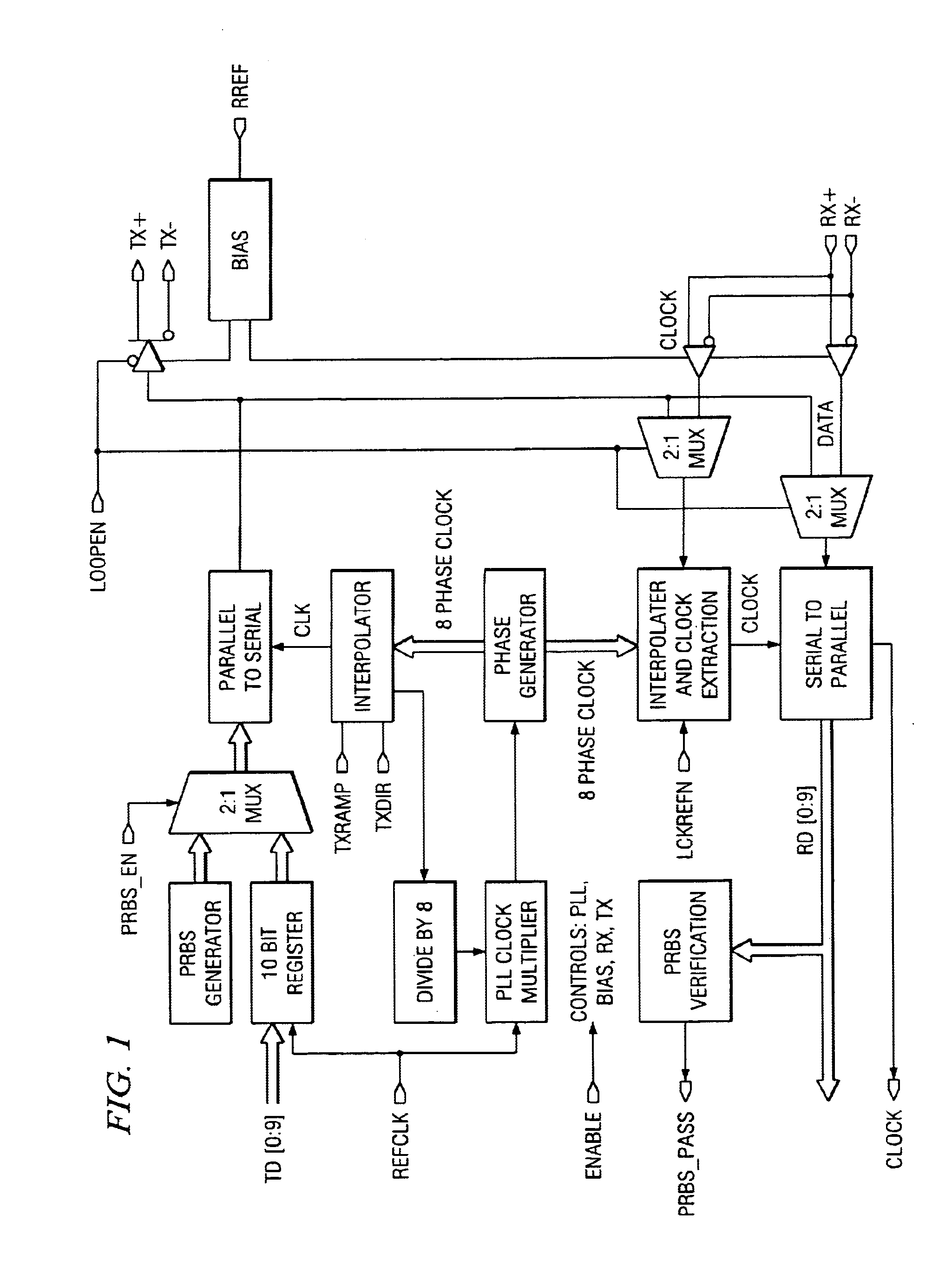
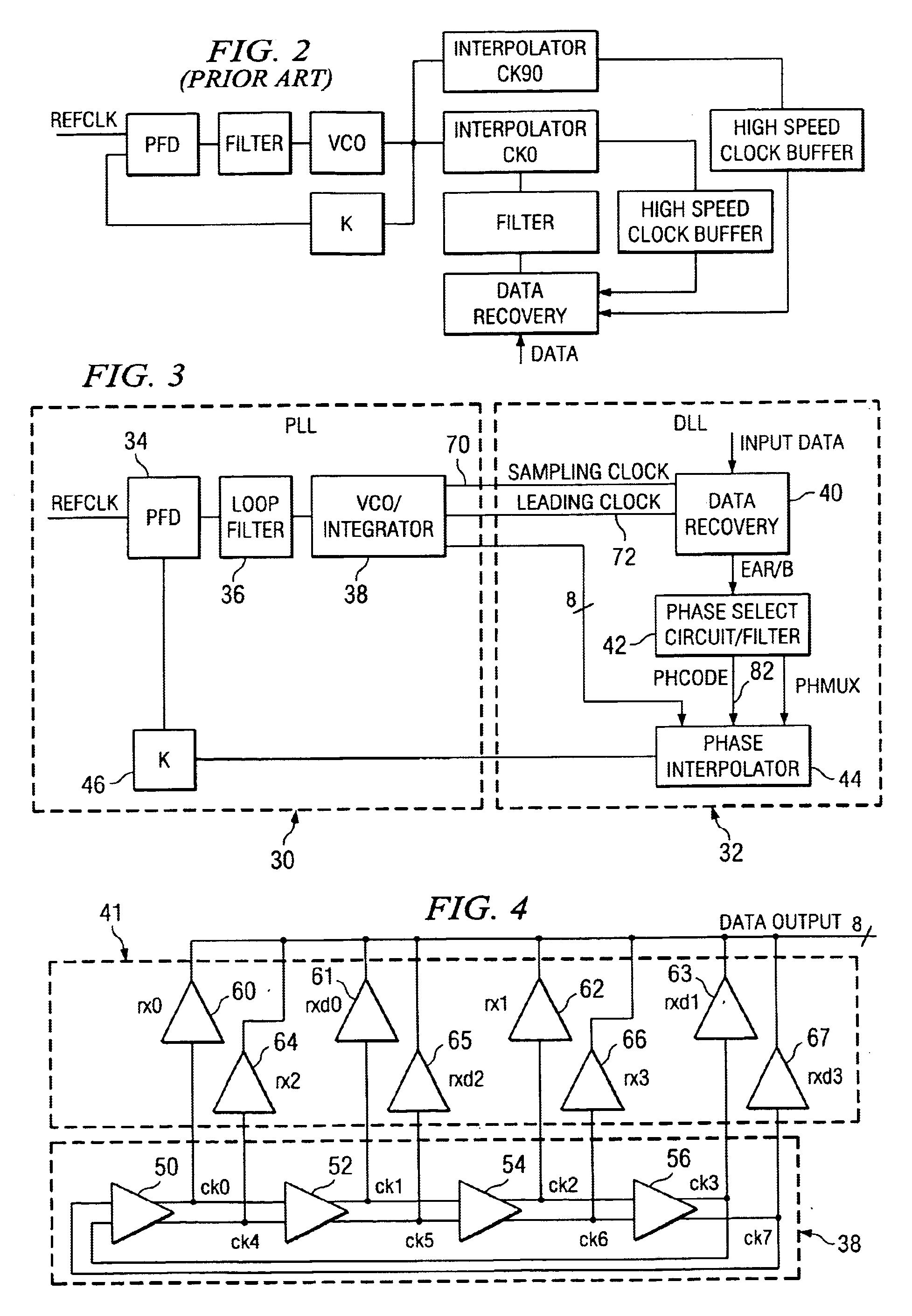
[0028]Architecturally, the transceiver uses a conventional PLL 30 frequency synthesizer on the Transmit side to generate high speed timing references. But on the receive side, according to a preferred embodiment of the invention, it uses an interpolator 44 and a bimodal data / clock receiver 40,41,42 to determine the ideal placement of the theoretical recovered clock. The phase select circuit 42 and phase interpolator 44 then picks one of the many, i.e. 8, phases of the Delay Locked Loop (DLL) 32 (driven by the Transmit PLL 30) that best matches the ideal and uses it as the recovered clock. This process continuously repeats itself as the incoming frequency is slightly off-frequency from the reference frequency.

[0029]The Phase Locked Loop (PLL) 30 design consists of a phase / frequency detector 34, a differential charge pump, an on chip loop filter capacitor 36, a replica-feedback current source bias, a differential voltage controlled oscillator (VCO) 38, differential to single end buffe...


PUM


Abstract

A time division multiplex data recovery system using a closed-loop phase lock loop (PLL) and delay locked loop (DLL) is disclosed. In other words, one closed loop comprises both a phase locked loop (PLL) and a delay locked loop (DLL) in a novel time division multiplex data recovery system. This new architecture comprises a 4 stage Voltage Controlled Oscillator (VCO) used to generate 8 clock signals, 45 degrees phase shifted from one another, for 8 receivers to do the oversampling. An interpolator tracks the received data signal and feeds it back to the Phase / Frequency Detector (PFD). The PFD has a second input of the reference clock which the PFD uses along with the interpolator input to correct the frequency of the PLL. The PLL operates at a high bandwidth. The DLL's bandwidth is several orders lower than the PLL. The DLL activates only a multiplexer and an interpolator continuously, thereby drawing a minimum amount of power.

Description

FIELD OF THE INVENTION[0001]This invention relates in general to time division multiplex data recovery systems and more specifically to a time division multiplex data recovery system using a close loop phase and delay locked loop.BACKGROUND OF THE INVENTION[0002]The TI Wizard is a full Duplex SERDES (Serialize-Deserialize) function plus the high speed differential I / O, the built-in self test (BIST) circuitry, and the phase locked loop (PLL) and delay locked loop (DLL) circuitry needed for timing references for the SERDES. A Wizard port supports data rates from 1.0 Gbaud through 2.5 Gbaud. It also includes comma detect circuitry used for the byte alignment of incoming bit stream.[0003]The Wizard performs basically a Fibre Channel operation: Transmit is 10-bits of 8b / 1 0b encoded data in and 1 bit at 10× the frequency differential out Receive is a 10× speed serial bit stream in and 10-bit 8b / 1 0b data out. The receive side also performs byte alignment. Wizard is also intended to be us...

Claims


Application Information

Patent Timeline
Patent Type & Authority Patents(United States)
IPC IPC(8): H04L7/033H03L7/099
CPCH03L7/0998H04L7/0337H04L7/0025
Inventor GU, RICHARD
Owner TEXAS INSTR INC
Why Eureka
Try Eureka