In situ venous valve device and method of formation

a venous valve and in situ technology, applied in the field of vascular valve devices and methods, can solve the problems of vericose vein formation, venous system and blood flow from the deep vein system, and the formation of vericose veins in the leg, and achieve the effect of simple design and ease of formation

Inactive Publication Date: 2005-06-07
DRASLER WILLIAM J +1
View PDF8 Cites 98 Cited by
  • Summary
  • Abstract
  • Description
  • Claims
  • Application Information

AI Technical Summary

Benefits of technology

[0028]It is further understood that the venous valve of the present invention can be constructed out of biological tissue such as venous tissue from animal sources, autologous tissue such as pericardium or venous tissue from another part of the body, or polymeric materials such as those used in vascular grafts. A venous valve of the present invention can be constructed as per the methods taught in the present disclosure and the resultant venous valve can be implanted interpositionally into a vein of a person at the venous site that requires a functioning venous valve. An embodiment such as this provides the advantage of simplicity of design and ease of formation.

Problems solved by technology

Incompetent valves can also lead to reflux of blood from the deep venous system to the superficial venous system and the formation of vericose veins.
Veins typically in the leg can become distended from prolonged exposure to excessive pressure and due to weaknesses found in the vessel wall causing the natural venous valves to become incompetent leading to retrograde blood flow in the veins.
Such veins no longer function to help pump or direct the blood back to the heart during normal walking or use of the leg muscles.
As a result, blood tends to pool in the lower leg and can lead to leg swelling and the formation of deep venous thrombosis and phlebitis.
The formation of thrombus in the veins can further impair venous valvular function by causing valvular adherence to the venous wall with possible irreversible loss of venous function.
Continued exposure of the venous system to blood pooling and swelling of the surrounding tissue can lead to post phlebitic syndrome with a propensity for open sores, infection, leading to possible limb amputation.
Repair and replacement of venous valves presents a formidable problem due to the low blood flow rate found in native veins, the very thin wall structure of the venous wall and the venous valve, and the ease and frequency of which venous blood flow can be impeded or totally blocked for a period of time.
These surgical techniques are highly technique dependent and difficult to perform by a highly trained vascular surgeon.
Blood stoppage for a period of time in contact with most foreign material can result in thrombus formation, and ensuing failure of any venous valve constructed of a polymeric material or some biomaterials.
The fixing process tends to cause such valves to be stiff and calcification has been known to occur at flexation sites.
Another problem with valves of this type is their lack of forming a stable endothelium with the resulting formation of thrombus when blood flow is impeded or temporarily blocked.
These devices have suffered problems associated with calcification, tissue degradation, tissue rejection, acute thrombosis, long term thrombosis, and valvular failure due to mechanical dysfunction.
The biomaterials used in the device of Camilli will not form a stable endothelium on the blood flow surface; due to the low blood flow and often times interrupted blood flow found within the venous system, this device will be prone to thrombosis and failure.
Also, many patients with venous problems do not have suitable valves onto which the appliance described by Laufer can be attached.
This significantly limits the patient population that can benefit from a device of this type.

Method used


Image

  • In situ venous valve device and method of formation
  • In situ venous valve device and method of formation
  • In situ venous valve device and method of formation

Examples


Embodiment Construction

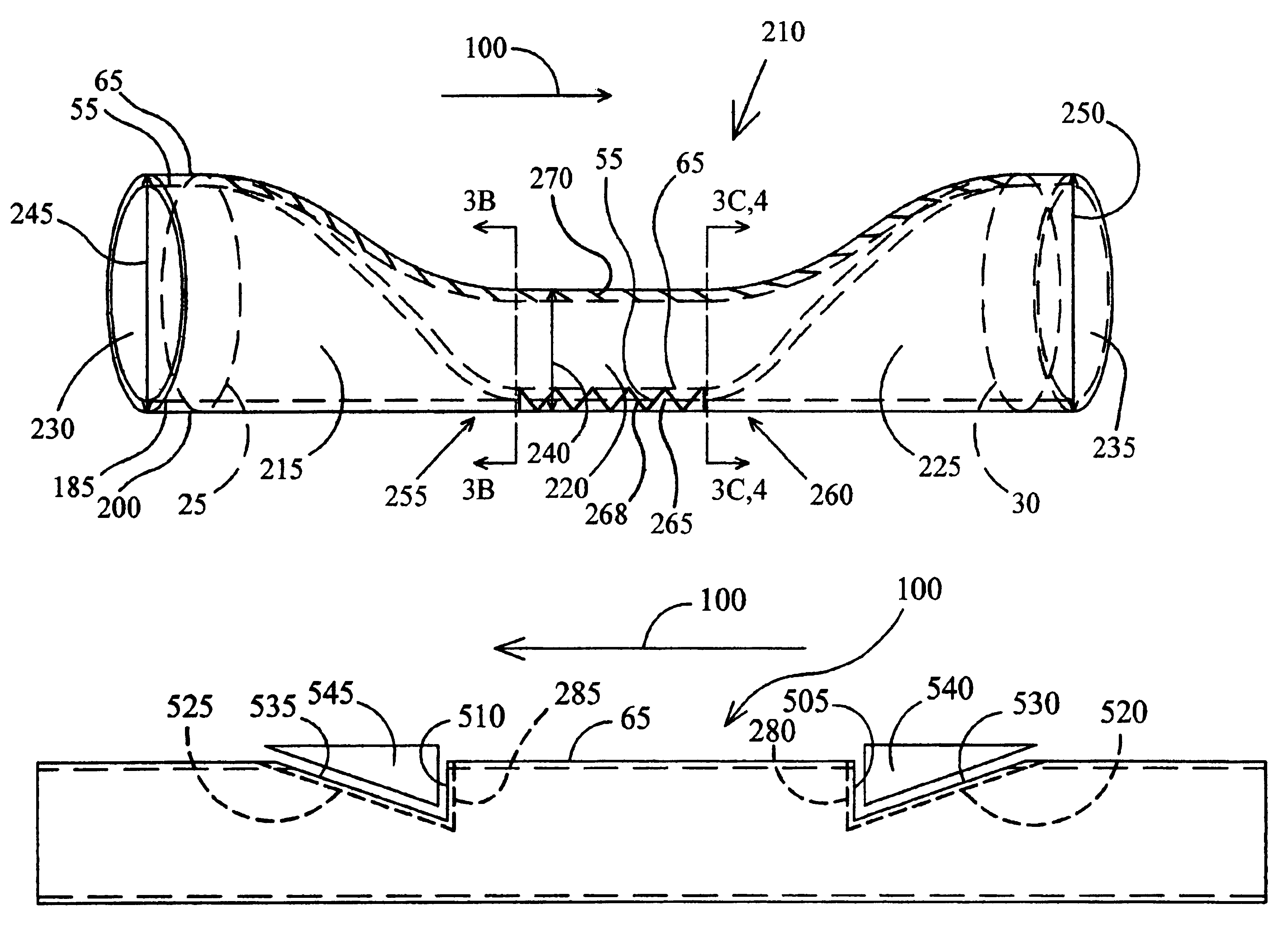
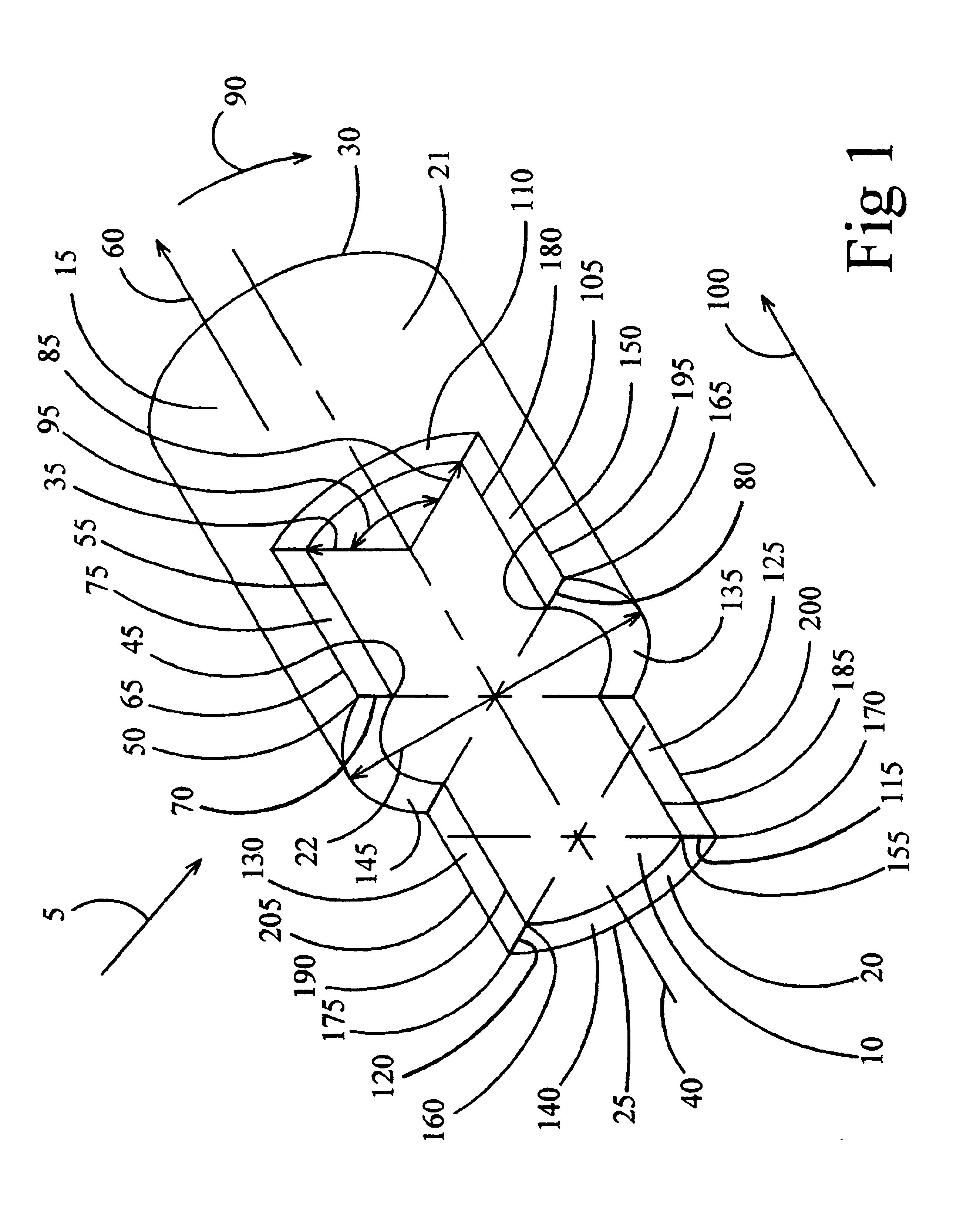
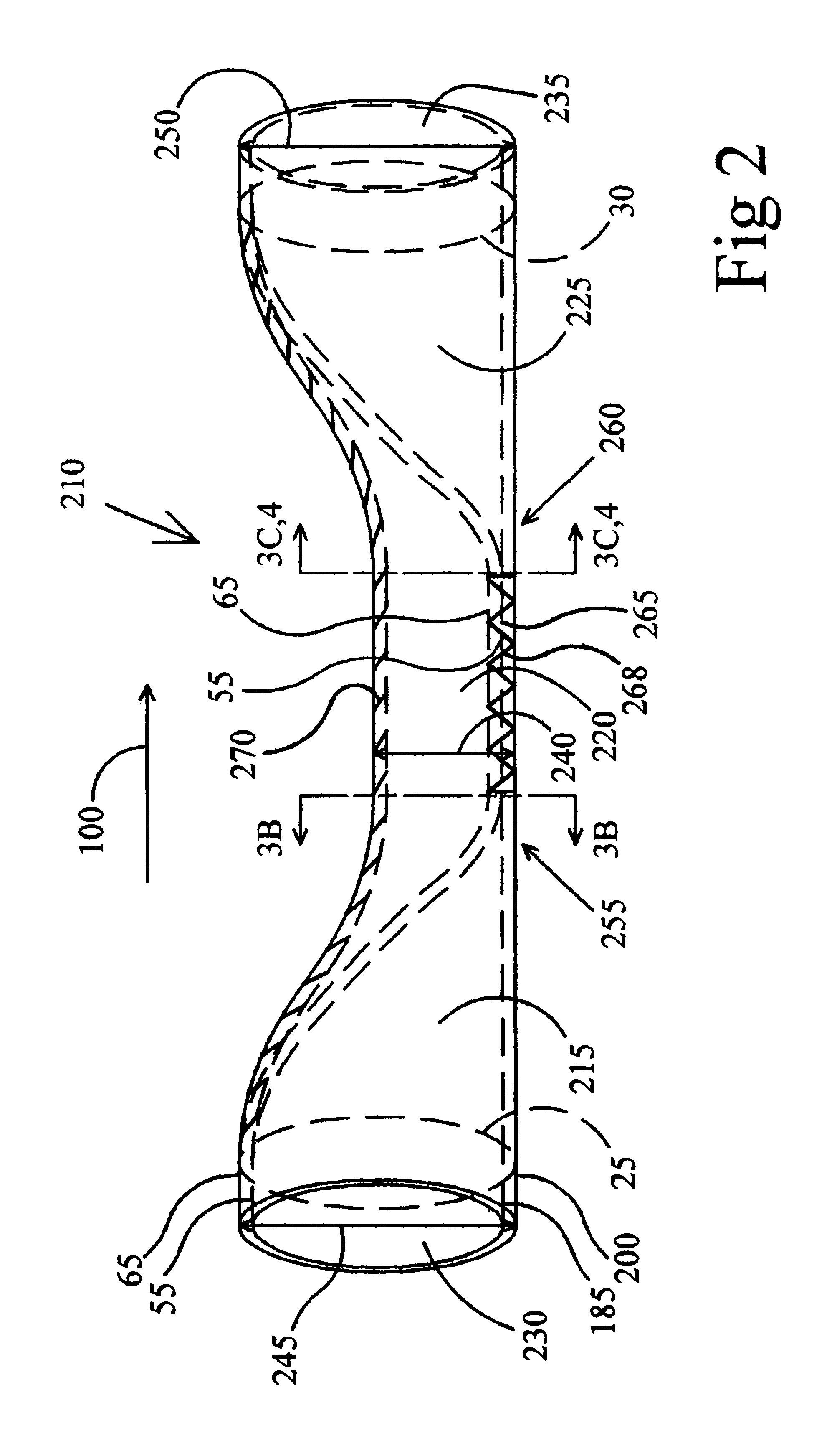
[0070]An embodiment of the venous valve of the present invention is formed from an approximately cylindrically shaped segment of distended native vein and the formation occurs with the vein in place in its naturally occurring in situ position. Once the venous valve has been formed, it can be contiguous with or it can be attached to native vein tissue both upstream and downstream from the venous valve. The structure of the venous valve and the methods for its construction are most easily and accurately described by referring to a cylindrical coordinate system to describe various properties or characteristics of the native vein and apply these characteristics to the formation of the venous valve of the present invention.

[0071]A venous valve of an embodiment of the present invention could also be formed from a segment of vein or other tissue taken from any suitable location within the same patient that requires the venous valve. The segment of vein containing the valve formed by the me...


PUM


Abstract

A venous valve device provides antegrade blood flow in venous vessels of the body having dysfunctional valves; it is formed in situ from autologous vein conduit not having a valve present locally. An overlap region is formed by attaching two opposing walls of the vein together in a generally axial direction forming two tubular regions. One region provides antegrade blood flow and the other region provides a sinus cavity that is filled during the initiation of retrograde blood flow. A valve cusp is formed by attaching vessel wall together forming a commissure that extends between the two overlap regions. A single valve cusp moves toward the sinus cavity to allow antegrade blood flow and moves away from the sinus cavity to block retrograde blood flow. The venous valve can also be formed from biological tissue from an autologous, heterologous, or other tissue source and implanted interpositionally at the site of valvular incompetancy.

Description

[0001]This is a continuation of U.S. application Ser. No. 09 / 814,265, filed Mar. 21, 2001 now U.S. Pat. No. 6,562,068, which is a continuation of U.S. application Ser. No. 09 / 328,835, filed Jun. 8, 1999 now U.S. Pat. No. 6,241,763.BACKGROUND OF THE INVENTION[0002]1. Field of Invention[0003]The present invention relates to a device and method for a vascular valve for the vascular system and more specifically for the venous vascular system of the human body and a method for forming the venous valve and more specifically for forming the venous valve from a native vein that may have been enlarged diametrically within the patient causing the naturally occurring venous valve to become incompetant.[0004]2. Description of Prior Art[0005]Venous valves are found within native venous vessels and are used to assist in returning blood back to the heart in an antegrade direction from all parts of the body. The venous system of the leg for example includes the deep venous system and the superficia...

Claims


Application Information

Patent Timeline
Patent Type & Authority Patents(United States)
IPC IPC(8): A61F2/24
CPCA61F2/2475A61F2/2412
Inventor DRASLER, WILLIAM J.THIELEN, JOSEPH M.
Owner DRASLER WILLIAM J
Why Eureka
Try Eureka